GAI-Tronics LE200, LE200-FSR, LE200-FLR Page/Party Line Extenders User Manual
Page 40
Pub. 42004-701L2F
M
ODEL
LE200
S
ERIES
W
ALL
-M
OUNT
P
AGE
/P
ARTY
®
L
INE
E
XTENDERS
P
AGE
38 of 50
f:\standard ioms - current release\42004 instr. manuals\42004-701l2f.doc
04/09
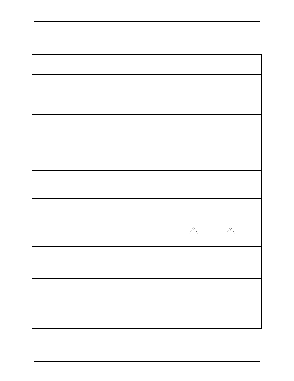
Table 41. Main Processing PCBA (Model 69443-xxx)
Refer to Figure 4 for component locations.
Designator Type
Function
J1
RJ45 receptacle
LVDS data “out”
J2
RJ45 receptacle
LVDS data “in”
J3
DB-25
connector
Connect to J1 on Input/Output Termination PCBA (Model 69442-
xxx) via 25-pin ribbon cable.
J4
DB-25
connector
Connect to J1 on Page/Party
®
Termination PCBA (Model 69441-
xxx) via 25-pin ribbon cable.
P1 N/A
Not
installed
P2
Post header
No connection - used during production testing of PC board)
P3 N/A
Not
installed
P4
Post header
No connection - used during production testing of PC board)
P5
Jumper clip
Page line ground fault detector enabled/disabled.
P6, P7
Jumper clip
Party line #5 off-hook detector enabled/disabled.
P8, P9
Jumper clip
Party line #4 off-hook detector enabled/disabled.
P10, P11
Jumper clip
Party line #3 off-hook detector enabled/disabled.
P12, P13
Jumper clip
Party line #2 off-hook detector enabled/disabled.
P14, P15
Jumper clip
Party line #1 off-hook detector enabled/disabled.
P16 Terminal
block
Page line monitor output - Terminals 1 and 3
No connection - Terminal 2
P17, P18
Terminal block
Power 48 V dc (+) - Terminal 1
Power 48 V dc (-) - Terminal 2
WARNING
Turn off power before connecting
and disconnecting.
P19
Terminal block
T1/E1 Data TX (ring) - Terminal 1
T1/E1 Data TX (tip) - Terminal 2
T1/E1 Data RX (ring) - Terminal 3
T1/E1 Data RX (tip) - Terminal 4
P20
Jumper clip
T1/E1 receive transformer center tap floating/grounded.
P21
Jumper clip
T1/E1 transmit transformer center tap floating/grounded.
PB1
Push-button
switch
Used to retrain the echo cancellation circuit.
SW1
Rotary HEX
switch
Used for diagnostic purposes. Set to 0 during normal operation