GAI-Tronics LE200, LE200-FSR, LE200-FLR Page/Party Line Extenders User Manual
Page 27
Pub. 42004-701L2F
M
ODEL
LE200
S
ERIES
W
ALL
-M
OUNT
P
AGE
/P
ARTY
®
L
INE
E
XTENDERS
P
AGE
25 of 50
f:\standard ioms - current release\42004 instr. manuals\42004-701l2f.doc
04/09
The T1/E1 and LVDS data link settings are described in the following paragraphs.
T1 Data Link Settings
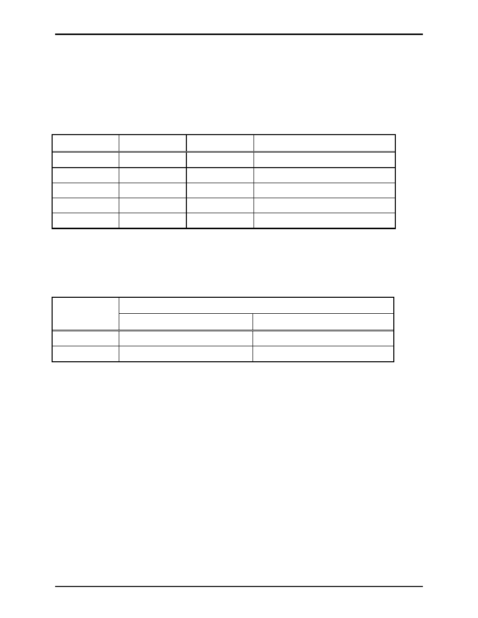
DIP switch, SW2, on the main PC board selects two line-length related parameters for the T1 format.
Line length refers to the distance between the two LE200s connecting over copper cable or the cable
distance between the LE200 and the fiber optic modem if using fiber optics to connect the line extenders.
Table 26. T1/E1 Line Length Setting on 69443-xxx PCBA
SW2-1 SW2-2 SW2-3 T1
Line
Length
Open (up)*
Open (up)*
Open (up)*
DSX-1 (0 to 133 feet)
Closed (down)
Open (up)
Open (up)
DSX-1 (133 to 266 feet)
Open (up)
Closed (down)
Open (up)
DSX-1 (266 to 399 feet)
Closed (down)
Closed (down)
Open (up)
DSX-1 (399 to 533 feet)
Open (up)
Open (up)
Closed (down)
DSX-1 (533 to 655+ feet)
N
OTES
: 1. Changes to this parameter take effect without cycling power.
2.
*Indicates
default
position.
3. These switches have no effect in E1 mode.
Table 27. Receive Equalizer Gain Limit Setting on 69443-xxx PCBA
Receive Equalizer Gain Limit
SW2-4
T1 Mode
E1 Mode
Open (up)*
-36 dB (long haul)
-12 dB (short haul)
Closed (down)
-15 dB (limited long haul)
-43 dB (long haul)
N
OTES
: 1. Changes to this parameter take effect without cycling power.
2.
*Indicates
default
position.