GAI-Tronics LE200, LE200-FSR, LE200-FLR Page/Party Line Extenders User Manual
Page 29
Pub. 42004-701L2F
M
ODEL
LE200
S
ERIES
W
ALL
-M
OUNT
P
AGE
/P
ARTY
®
L
INE
E
XTENDERS
P
AGE
27 of 50
f:\standard ioms - current release\42004 instr. manuals\42004-701l2f.doc
04/09
Headers P20 and P21 control the grounding of the T1/E1 lines. Grounding the T1/E1 lines may reduce
emissions if that is an installation concern.
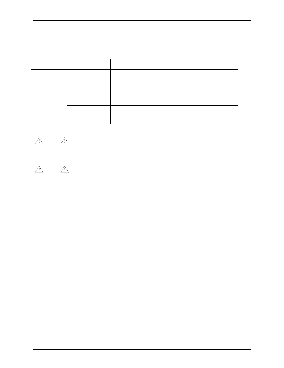
Table 31. T1/E1 Line Grounding on 69443-xxx PCBA
Header
Shorting Clip
Grounding Condition
P20
1-2*
T1/E1 Rx line floating.
2-3
T1/E1 Rx line grounded.
Removed
T1/E1 Rx line floating.
P21
1-2*
T1/E1 Tx line floating.
2-3
T1/E1 Tx line grounded.
Removed
T1/E1 Tx line floating.
*Indicates default position.
NOTE
Do not connect the T1/E1 transmit signal to the T1/E1 receive signal on the same
Model LE200. Doing so creates a feedback path that usually results in extremely loud oscillations
on the page line and the party lines. The contact outputs may also activate.
NOTE
Do not ground the T1/E1 lines at both ends. Doing so will create a ground loop.
An unused T1 connection can be left open (not terminated).