GAI-Tronics LE200, LE200-FSR, LE200-FLR Page/Party Line Extenders User Manual
Page 34
Pub. 42004-701L2F
M
ODEL
LE200
S
ERIES
W
ALL
-M
OUNT
P
AGE
/P
ARTY
®
L
INE
E
XTENDERS
P
AGE
32 of 50
f:\standard ioms - current release\42004 instr. manuals\42004-701l2f.doc
04/09
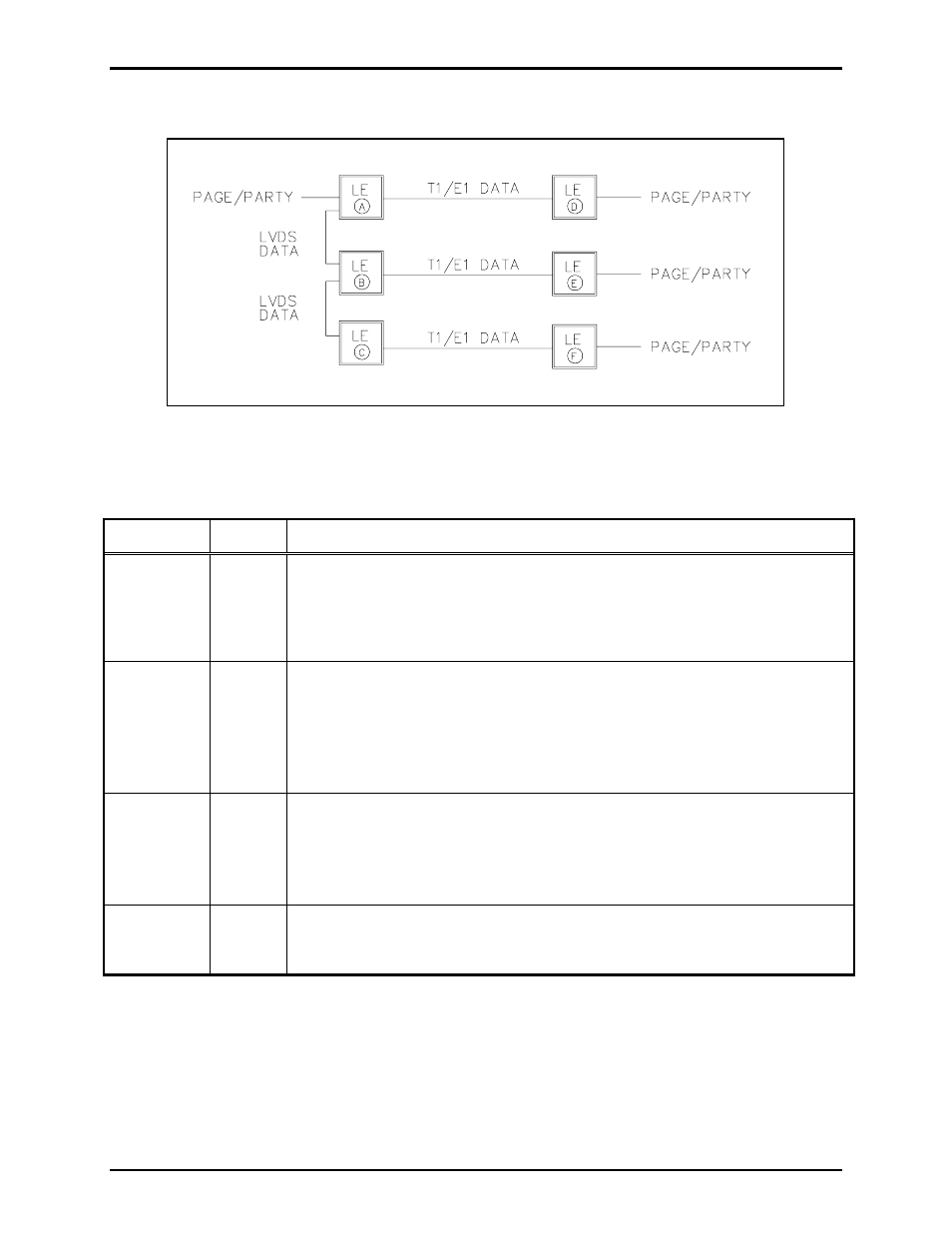
Point to Multi-point Page/Party
®
System Connection
Figure 11. Point to Multi-point Page/Party
®
System Connection
Table 37. Point to Multi-point Page/Party
®
System Connection Table
Parameter Switch
Configuration
Description
T1 Line
Length
SW2
Determined by installation distance between each pair of line extenders:
• A to D
• B to E
• C to F
T1/E1 Clock
Source
SW3-1
SW3-2
• Units A, B, and C are the master clock sources: SW3-1 (open) SW3-2
(open)
• Unit D uses the T1/E1 clock from Unit A: SW3-1 (closed) SW3-2 (closed)
• Unit E uses the T1/E1 clock from Unit B: SW3-1 (closed) SW3-2 (closed)
• Unit F uses the T1/E1 clock from Unit C: SW3-1 (closed) SW3-2 (closed)
LVDS
Clock
Source
SW3-3
SW3-4
LVDS clock is used between units A, B and C.
• Unit A - “in” disabled, “out” enabled: SW3-3 (open) SW3-4 (closed)
• Unit B - “in” enabled, “out” enabled: SW3-3 (closed) SW3-4 (closed)
• Unit C - “in” enabled, “out” disabled: SW3-3 (closed) SW3-4 (open)
Mute
Analog
Lines
SW6-4
Units B and C are muted since no Page/Party
®
cable is connected:
SW6-4 (closed).