GAI-Tronics LE200, LE200-FSR, LE200-FLR Page/Party Line Extenders User Manual
Page 28
Pub. 42004-701L2F
M
ODEL
LE200
S
ERIES
W
ALL
-M
OUNT
P
AGE
/P
ARTY
®
L
INE
E
XTENDERS
P
AGE
26 of 50
f:\standard ioms - current release\42004 instr. manuals\42004-701l2f.doc
04/09
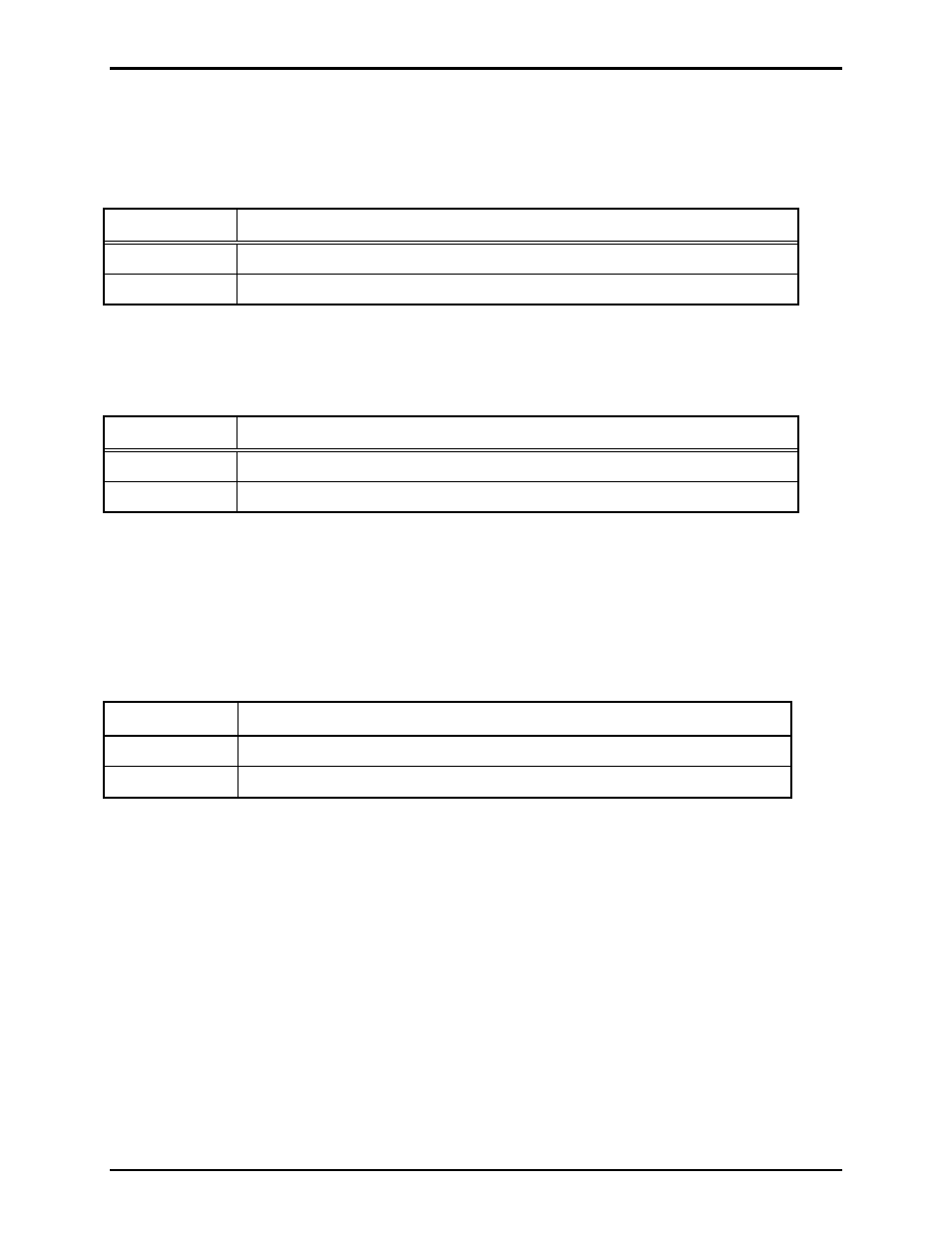
DIP switch SW3 selects T1/E1 clock related parameters. For each pair of line extenders, only one line
extender can be clock source (master).
Table 28. Use T1/E1 Clock as Board’s Master Clock Source Setting on 69443-xxx PCBA
SW3-1
T1/E1 Clock as Board’s Master Clock Source
Open*
The recovered clock is not the board’s master clock source.
Closed
The recovered clock is the board's master clock source.
N
OTES
: 1. Changes to this parameter take effect after cycling power.
2.
*Indicates
default
position.
Table 29. Use the Board’s Master Clock as the T1/E1 Transmit Clock Setting on 69443-xxx PCBA
SW3-2
Use the Board’s Master Clock as the T1/E1 Transmit Clock
Open*
The board’s master clock is the transmit clock (clock master).
Closed
The remote (recovered) clock is the transmit clock (clock slave).
N
OTES
: 1. Changes to this parameter take effect after cycling power.
2.
*Indicates
default
position.
DIP switch, SW5, on the main PC board provides the selection of which data link format is to be used for
the digital audio transmission. The T1 (1.544 Mbps) format is most commonly used in North America.
The E1 (2.048 Mbps) format is most commonly used in Europe. It is important that these settings match
between the connected LE200s and any interface equipment between.
Table 30. Digital Audio Format Setting on 69443-xxx PCBA
SW5-8
Digital Audio Format
Open*
T1 Mode (1.544Mbps, 24-channel)
Closed
E1 Mode (2.048Mbps, 32-channel)
N
OTES
: 1. Changes to this parameter take effect after cycling power.
2.
*Indicates
default
position.