GAI-Tronics LE200, LE200-FSR, LE200-FLR Page/Party Line Extenders User Manual
Page 30
Pub. 42004-701L2F
M
ODEL
LE200
S
ERIES
W
ALL
-M
OUNT
P
AGE
/P
ARTY
®
L
INE
E
XTENDERS
P
AGE
28 of 50
f:\standard ioms - current release\42004 instr. manuals\42004-701l2f.doc
04/09
LVDS Data Link Settings
DIP switch, SW3, selects the LVDS related parameters which are the LVDS “in” clock and the LVDS
“out” port enable or disable. The LVDS “in” port is disabled unless it is receiving a signal from LVDS
“out” of a different Model LE200.
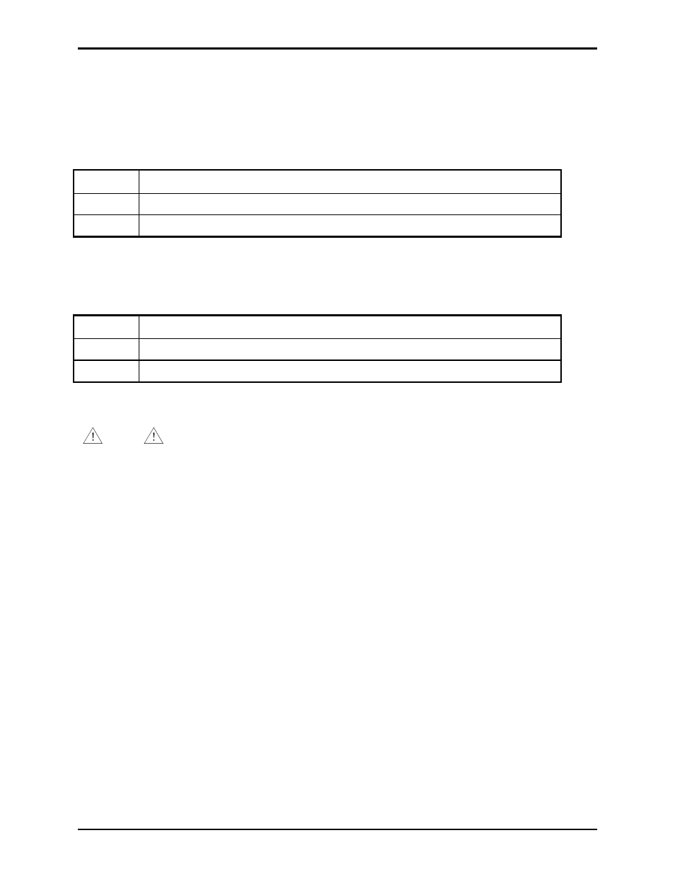
Table 32. Use the LVDS “in” Clock as Board’s Master Clock Source Setting on 69443-xxx PCBA
SW3-3
LVDS “in” as Board’s Master Clock Source
Open*
The LVDS “in” clock is not the board’s master clock source.
Closed
The LVDS “in” clock is the board’s master clock source.
N
OTES
: 1. Changes to this parameter take effect after cycling power.
2.
*Indicates
default
position.
Table 33. Enable LVDS “out” Setting on 69443-xxx PCBA
SW3-4 Enable
LVDS
“out”
Open*
LVDS “out” is disabled.
Closed
LVDS “out” is enabled.
N
OTES
: 1. Changes to this parameter take effect without cycling power.
2.
*Indicates
default
position.
NOTE
Do not connect LVDS “in” to LVDS “out” on the same Model LE200. Doing so
creates a feedback path that usually results in (extremely loud) oscillations on the page line, all party
lines, and possibly the contact outputs.
Unused LVDS ports can be left open.
LVDS Port Indicators
Each LVDS port has two LEDs. The green LED is ON when the LE200 detects a signal from the remote
LE200 on that LVDS port. The yellow/orange LED is ON when the local LE200 is the source of page
line data (SmartSeries FSK or 50 kHz VLC) out of that LVDS port.