Flowserve ISC User Manual
Page 11
6.2 Lubricate the shaft or
sleeve lightly with silicone
lubricant unless otherwise
specified.
6.3 Tighten the Centering Tab
screws
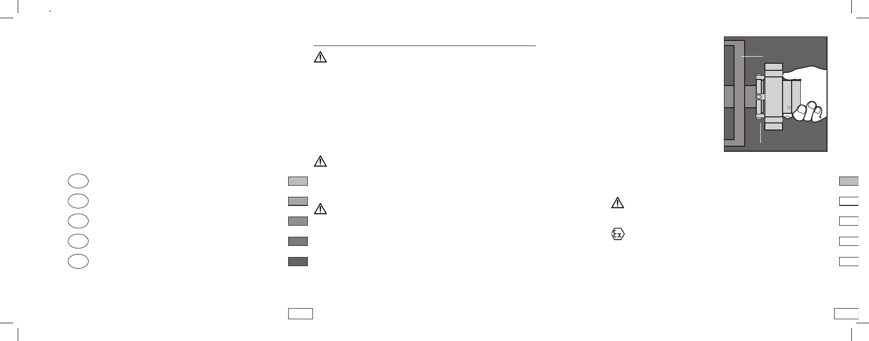
6.4 Install the complete ISC
cartridge assembly onto the
shaft or sleeve with the cen-
tering tabs near the bearing
housing.
See Figure 3.
For some pumps it may be required to remove the bearing frame
before installing the cartridge seal.
Vibrations must be prevented from transferring to the installed
ISC during operation, e.g. through structural measures imple-
mented on the machine.
The machine to take the ISC must be earthed in accordance with
the applicable regulations for electrical installations (e.g. VDE
rules) to conduct away any electrostatic build-up and so prevent
spark formation.
6.5 Install the pump back plate (seal chamber) and bolt it in place on
the bearing frame.
See Figure 4.
6. ISC Installation - Single Seal Design
The installation chamber for the mechanical seal must be checked
against the corresponding drawing and table of dimensions.
It must be ensured that all dimensions, surface qualities, and
tolerances (e.g. concentricity, run-out, fits) are observed. The
specifications under e.g. ISO 2049 or API 62, DIN 26,
FLOWSERVE publication FSD 0, FLOWSERVE publication
FSD27 must be observed.
NOTE: No seal setting measurements are needed to install the seal.
Instructions are for vertically split case end-suction ANSI pumps.
Modification of the procedure may be required for other style
pumps. Consult Flowserve.
Take care that seal cartridge or components of the seal are
handled and carried safely during installation of mechanical seal
and that the ergonomic principles are followed. In order to prevent
personal injuries the operator should also wear protective clothing
as per the plant’s safety regulations.
Precautions must be taken for parts of the mechanical seal that
will be used as support to step on during assembly operations.
These parts must be protected against slipping, stumbling or fall-
ing (for example by using a strut).
6. Tools needed for installation:
* An open end wrench for the gland bolt nuts
* /" (imperial sizes) or 3 mm (metric sizes). Allen wrench (provided)
* 3/6" (imperial sizes) or 5 mm (metric sizes). Allen wrench (pro-
vided) for sizes >2.500" (65 mm)
20
ISC Dimensional Data
ISC Abmessungen
Encombrement des garnitures ISC
Dimensioni delle tenute ISC
Dimensiones ISC
GB
D
F
I
E
Bearing Frame
Setting Device
Figure 3
2