B.5 packet structure, B.5.1 start of packet, B.5.2 target (base) address – Comtech EF Data PCB-4300 User Manual
Page 81
PCB-4300 1:2 Phase Combiner
Revision
2
Appendix B
MN/PCB4300.IOM
B–3
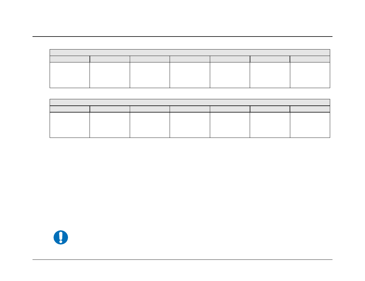
B.5
Packet Structure
Controller-to-Target
Start of Packet
Target Address
Address Delimiter
Instruction Code
Code Qualifier
Optional Arguments
End of Packet
<
ASCII code 60
(1 character)
(4 characters)
/
ASCII code 47
(1 character)
(3 characters)
= or ?
ASCII codes 61 or
63
(1 character)
(n characters)
Carriage Return
ASCII code 13
(1 character)
Example: <0412/MUT=1{CR}
Target-to-Controller
Start of Packet
Target Address
Address Delimiter
Instruction Code
Code Qualifier
Optional Arguments
End of Packet
>
ASCII code 62
(1 character)
(4 characters)
/
ASCII code 47
(1 character)
(3 characters)
=, ?, !, or *
ASCII codes
61, 63, 33, or 42
(1 character)
(From 0 to n
characters)
Carriage Return,
Line Feed
ASCII codes 13,10
(2 characters)
Example: >0412/MUT={CR}{LF}
B.5.1 Start Of Packet
Controller-to-Target: This is the character ‘<’ (ASCII code 60).
Target-to-Controller: This is the character ‘>’ (ASCII code 62).
Because this is used to provide a reliable indication of the start of packet, these two characters may not appear anywhere else within the
body of the message.
B.5.2 Target (Base) Address
Up to 9,999 devices can be uniquely addressed. In both EIA-232 and EIA-485 applications, the permissible range of values is 1 to 9999. It
is programmed into a Target unit using serial remote control.
IMPORTANT
The Controller sends a packet with the address of a Target – the destination of the packet. When the Target
responds, the address used is the same address, to indicate to the Controller the source of the packet. The
Controller does not have its own address.