2 led status operation – Comtech EF Data PCB-4300 User Manual
Page 34
PCB-4300 1:2 Phase Combiner
Revision 2
Operation and Adjustment Procedures MN/PCB4300.IOM
3–4
3.2.2 LED Status Operation
The PCB-4300 1:2 Phase Combiner features four
Light-Emitting Diode (LED) indicators. Each LED
provides the user with visual cues to the operational,
online, and offline status of the system.
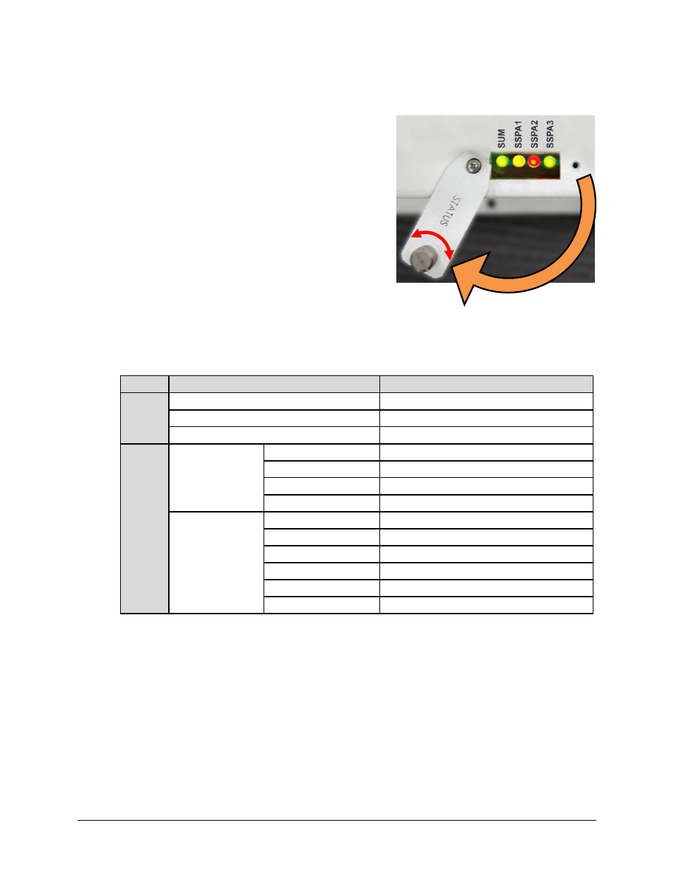
Figure 3-3 illustrates the location of the LED
indicators. Located on the top of the PCB-4300
enclosure under a pivoting protective plate, the LEDs
may be viewed by loosening the captive screw that
keeps the plate in place; the user can then swing the
plate away to reveal the LED display window.
The behavior of the LEDs, as they appear under varying operational conditions, is as follows:
LED
Color / Behavior
Description
SUM
(LED 1)
Green
Phase Combiner has no summary fault.
Red (blinking)
A switch fault has occurred.
Red (constant)
A Summary Fault has occurred.
SSPA 1
(LED 2)
-or-
SSPA 2
(LED 3)
-or-
SSPA 3
(LED 4)
Phase-Combine
mode (RED=1)
Green (constant)
SSPA is unfaulted, unmuted and online.
Orange (constant)
SSPA is unfaulted but muted, and online.
Red (blinking)
SSPA is faulted and has gone offline.
Red (constant)
SSPA is faulted but online.
Non Phase-
Combine mode
(RED=0)
Green (constant)
SSPA is unfaulted, unmuted and online.
Green (blinking)
SSPA is unfaulted, unmuted and offline.
Orange (constant)
SSPA is unfaulted but muted, and online.
Orange (blinking)
SSPA is unfaulted but muted, and offline.
Red (constant
SSPA is faulted but online.
Red (blinking)
SSPA is faulted and has gone offline.
Figure 3-3. PCB-4300 LED Status Panel