3 theory of operation, 1 phase and gain equalization – Comtech EF Data PCB-4300 User Manual
Page 18
PCB-4300 1:2 Phase Combiner
Revision 2
Introduction
MN/PCB4300.IOM
1–4
• The output waveguide combining system consists of balanced waveguide lengths, two
waveguide transfer switches, a “Magic-Tee” combiner with termination, and couplers for
test and alignment.
1.3
Theory of Operation
As mentioned previously, phase combining is a common technique to increase the available output
power of an amplifier system. Referring back to the Figure 1-2 system block diagrams, when two
signals of equal phase and amplitude are fed into the “Magic-Tee” combiner, the individual power
of each SSPA is summed at the output port and cancelled in the termination port.
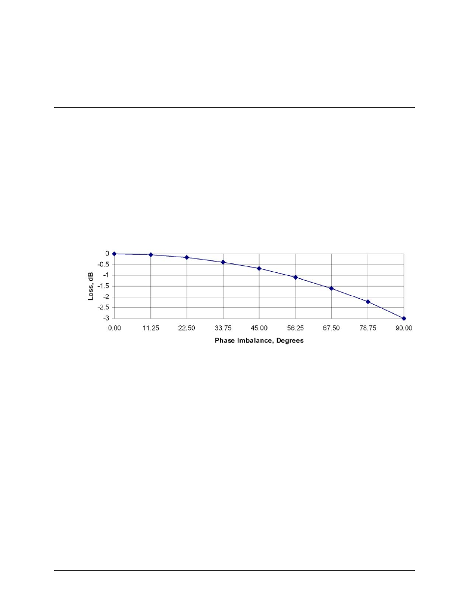
In real systems, the phase and amplitude of the two signals are never exactly equal, so there is a
small amount of power that is absorbed by the load termination. This terminated port is
sometimes referred to as the “wasted” power port. In practice, however, it is possible to keep
phase and amplitude imbalances at low enough levels such that overall combining losses are only
in the 0.2 to 0.5 dB range.
Figure 1-3 shows the effects of phase imbalance on the power combining efficiency.
Figure 1-3. Combining Loss vs. Phase Imbalance Summary of Specifications
1.3.1
Phase and Gain Equalization
Note: Phase and gain equalization are performed at the factory, and no user intervention is
required unless an amplifier or other critical system component, such as the phase combiner box,
needs replaced. The following paragraphs are provided for informational purposes; for
operational and alignment information, refer to Chapter 3. OPERATION
AND
ADJUSTMENT
PROCEDURES.
Naturally, three separate amplifiers are likely to have different phase and gain characteristics. The
PCB-4300 1:2 system is designed such that the phase difference between the three amplifier paths
is compensated by adjusting the phase shifter in the Phase Combiner Control Box. This is done at
the factory for the full amplifier bandwidth and should not normally require further adjustment in
the field unless an amplifier has been replaced.