Cable connections for redundant system operation, Figure 6. cable interconnect diagram – Comtech EF Data UT-4579 User Manual
Page 29
UT4579 X-Band Up Converter
MN/UT4579.IOM
Installation
Rev. 0
13
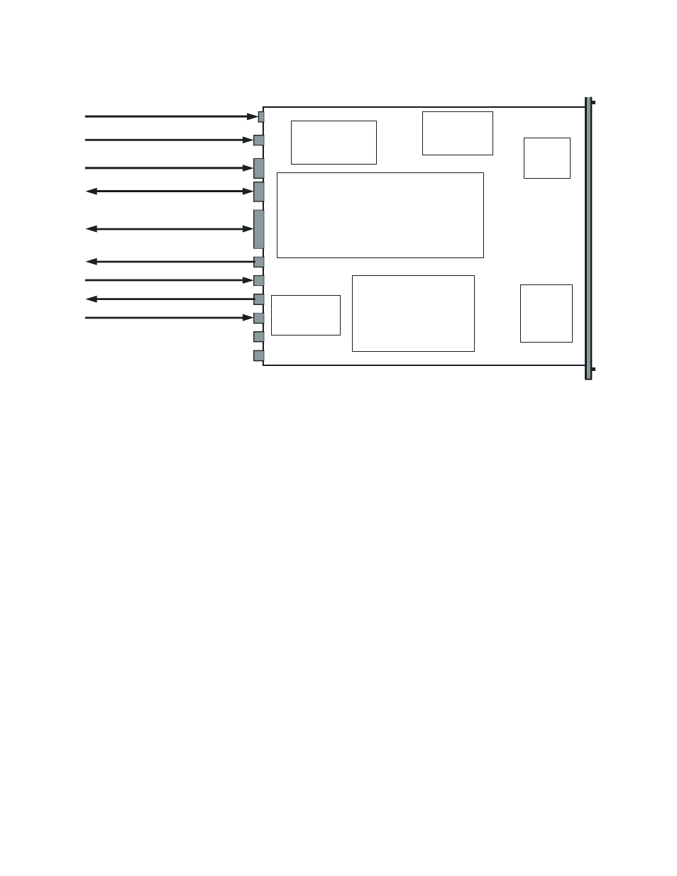
Power
Supply
Reference
Oscillator
Fine
Step
Module
Sum
Loop
Module
Monitor & Control Assembly
Receive
I/O Switch
Module
RF Converter
Prime Power Cord Input
5/10 MHz Ref. Osc. Input
J2
P1
J1
J3
J4
J6
J8
J5
J7
J9
Summary Fault Relay Output
Serial Comm. Interface
(EIA-485 / EIA-232C)- COM 1
High Speed Bus (HSB)
IF Output (IF)
IF Loop Input (LP IN)
IF Loop Output (LP OUT)
RF Input (RF)
(Not Used)
(Not Used)
Figure 6. Cable Interconnect Diagram
2.4.5 C
ABLE
C
ONNECTIONS
F
OR
N
ON
-R
EDUNDANT
S
YSTEM
O
PERATION
In non-redundant converter configuration the converter has an Input/Output Module
(IOM-XX) for the RF input and the IF Output. A converter with a Transmit Switch
Module may be operated in a non-redundant configuration if an IOM is unavailable.
Figure 7 is an illustration of the converter cable connections with an IOM installed.
Figure 8 is an illustration of the converter cable connections with a TSM installed.
2.4.6 C
ABLE
C
ONNECTIONS
F
OR
R
EDUNDANT
S
YSTEM
O
PERATION
In subsystems where a redundant converter configuration is used, the backup converter
has an Input/Output Module (IOM-XX) and the online converters have Transmit Switch
Modules (TSM-XX) which switch to the backup converter when a fault is detected.
Redundant system operation is discussed in Appendix A, Redundant System Operation.