Comtech EF Data KST-12025 User Manual
Page 95
KST-12025 Ku-Band Satellite Terminal
Theory of Operation
Rev. 1
5–9
5.1.5.5
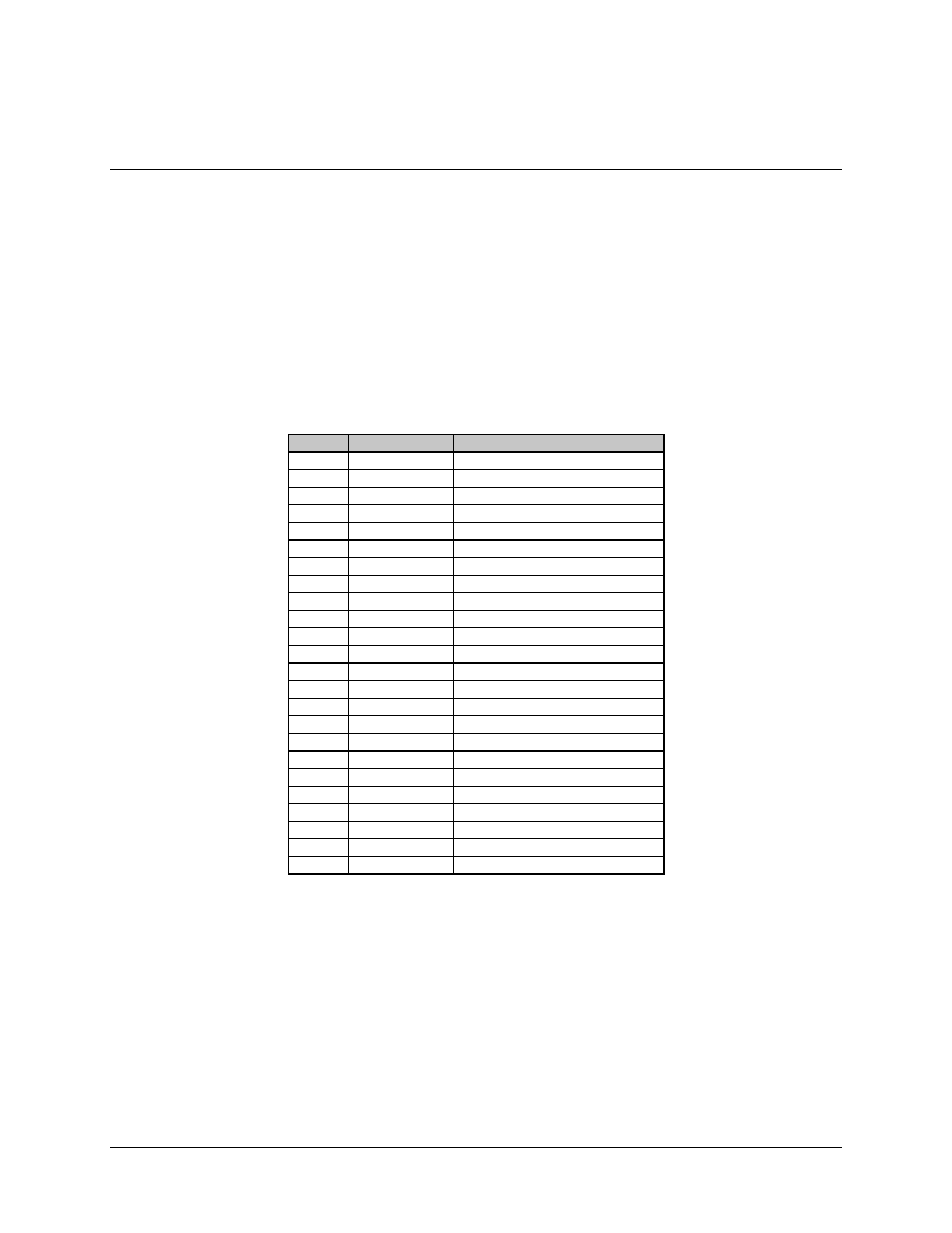
Keypad Display, 24-Pin (12 x 2) Ribbon Connector (J5)
The front panel display/keypad is an optional feature which allows the user to configure
and monitor status of the terminal locally.
All functions are also accessible from the remote port.
When this option has been installed, the 24-pin ribbon connector will be routed from J5
of the M&C PCB to the keypad/display assembly.
The connection pinouts are as follows:
Pin #
Name
Description
1
/A0
Address data line 0 inverted
3
/A2
Address data line 1 inverted
5
A2
Address data line 2
7
A3
Address data line 3
9
A4
Address data line 4
11
A5
Address data line 5
13
/D0000
Address D000 inverted
15
/BFR READ
Buffered read inverted
17
/BFR WRITE
Buffered write inverted
19
SPARE
21
/KB INTRPT
Reserved for KB interrupt
23
GND
Ground
2
+5V
+5V
4
SPARE
6
BFRD AD0
Buffered address data line 0
8
BFRD AD1
Buffered address data line 1
10
BFRD AD2
Buffered address data line 2
12
BFRD AD3
Buffered address data line 3
14
BFRD AD4
Buffered address data line 4
16
BFRD AD5
Buffered address data line 5
18
BFRD AD6
Buffered address data line 6
20
BFRD AD7
Buffered address data line 7
22
SPARE
24
SPARE