Fault isolation, 2 fault isolation – Comtech EF Data KST-12025 User Manual
Page 108
Maintenance
KST-12025 Ku-Band Satellite Terminal
6–2
Rev. 1
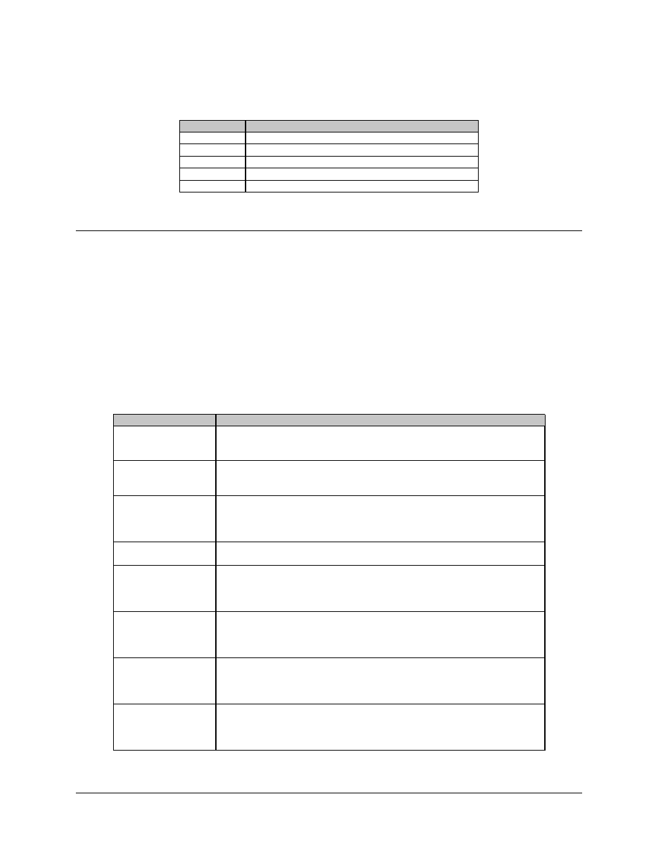
Table 6-2. Test Points
Test Point
Description
TP3
12.5V input power voltage.
TP6
Down converter AGC voltage (0 to 4V).
TP7
Up converter attenuator voltage (0 to 4V).
TP8
High-power amplifier AGC voltage (0 to 4V).
TP9
Up converter AGC voltage (0 to 4V).
6.2 Fault
Isolation
Once the terminal has been set up for operation, troubleshooting faults can be
accomplished by monitoring the terminal faults either remotely or via the optional front
panel/keypad and display.
System faults are reported in the Faults menu.
The following list should be used in isolating a problem and deciding the appropriate
action to be taken. Refer to Figure 6-1 and Figure 6-2 for the locations of the various
modules mentioned in this list.
Fault
Possible Problem and Action
+5 VOLT
+5V power supply fault. Indicates the +5V power supply on the M&C board is at
a high or a low voltage condition. Allowable level variation is ± 5% Check for a
short on the +5V line or faulty connection at P3 on the M&C.
+12 VOLT
+12V supply fault. Indicates the +12V supply is at a high or low voltage
condition. Check for a short on the +12V line or faulty connections between any
of the internal modules.
HPA
High-power amplifier fault. Check for a loose connector at P12, then replace the
high-power amplifier. The high-power amplifier is not intended to be opened in
the field. Once the problem has been isolated, the transmitter must be turned back
on.
LNA
Low Noise Amplifier fault. Check the RF cable to the LNA, then replace the
LNA.
U/C LOCK
U/C LO V
t
-S TUN
U/C LO V
t
-V TUN
Up Converter Lock fault. Check for loose connections at P7, P8, and P4. Also
check all RF coaxial connectors on the U/C synthesizer and U/C board before
replacing modules. Once the problem has been isolated, the transmitter must be
turned back on.
D/C LOCK
D/C LO V
t
-V TUN
Down converter tuning fault. Check for loose connections at P10, P11, and P4.
Also check all RF coaxial connectors on the D/C synthesizer and D/C before
replacing the modules. Once the problem has been corrected, the transmitter must
be turned back on.
IF LOCK
IF Lock fault. Check for loose connections at P9 and P4. Also, check all RF
coaxial connectors on the IFLO module. If all connections are good, replace the
IFLO module. Once the problem has been isolated, the transmitter must be turned
back on.
IF TUN
IF Tuning fault. Check for loose connections at P9 and P4. Also check all RF
coaxial connectors on the IFLO module. If all connections are good, replace the
IF local oscillator module. Once the problem has been isolated, the transmitter
must be turned back on.