2 fault isolation – Comtech EF Data CST-5005 User Manual
Page 90
Maintenance
CST-5005 C-Band Satellite Terminal
6–2
Rev. 1
Name
Color
Description
D/C FLT
Red
Illuminates when D/C is not connected, or is faulted.
LNA PWR
Yellow
Illuminates when LNA power is ON.
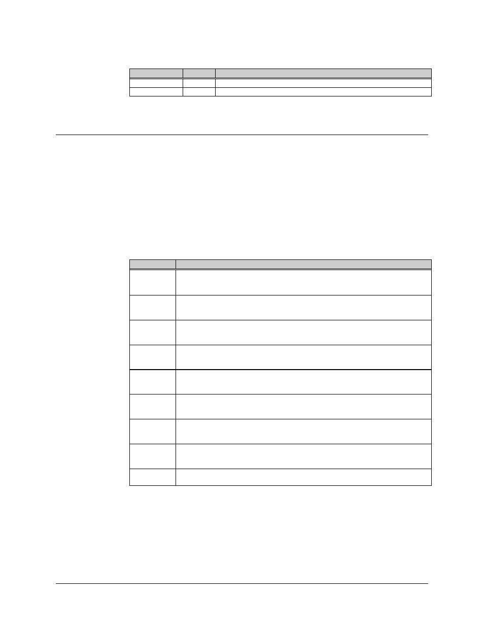
6.2 Fault Isolation
Once the terminal has been set up for operation, troubleshooting faults can be
accomplished by monitoring the terminal faults remotely, via the optional KP-10 external
keypad, or by removing the cover and observing the LEDs on the M&C board.
The following table should be used in isolating a problem and deciding the appropriate
action to be taken.
Refer to Figures 6-1 and 6-2 for the locations of the various modules mentioned in this
list.
Fault
Possible Problem and Action
+5 VOLT
+5V power supply fault. Indicates the +5V power supply on the M&C board is at
a high or a low voltage condition. Allowable level variation is
±
5%. Check for a
short on the +5V line, or faulty connection at P4 on the M&C board.
+12 VOLT
+12V supply fault. Indicates the +12V power supply is at a high or low voltage
condition. Check for a short on the +12V line, or faulty connections between any
of the internal modules.
HPA
High Power Amplifier fault. Verify that the RF output is programmed ON. Check
for a loose connection at J3. If acceptable, replace the U/C-HPA module. Once
the problem has been corrected, the transmitter must be turned back ON.
OSC
Reference Oscillator fault. Check RF cable from reference oscillator module to
synthesizer/IFLO module. Check P4 on M&C and P13 on oscillator module. If
acceptable, replace the reference oscillator module.
D/C
Down Converter fault. Indicates either faulty connection of module or missing
temperature/frequency compensation. Check P4 (at M&C) and J8 (at U/C). If
acceptable, replace D/C module.
U/C
Up Converter fault. Indicates either faulty connection of module or missing
temperature/frequency compensation. Check J3 (at M&C) and P12 (at U/C). If
acceptable, replace U/C-HPA module.
SYNTH
Synthesizer fault. Indicates that the synthesizer if out of lock. Check the RF
cable from reference oscillator module to the synthesizer/IFLO module. Check
J9, J8, and P7. If acceptable, replace the synthesizer/IFLO module.
IFLO
IF Local Oscillator fault. Indicates the IFLO is out of lock. Check the connection
of the RF cable from reference oscillator module, J9, J8, and P7. If acceptable,
replace the synthesizer/IFLO module.
LNA
Low Noise Amplifier fault. Check the RF cable from the LNA to J4 of the
RFT-505 terminal. If acceptable, replace the LNA.