1 specifications, 2 theory of operation – Comtech EF Data CST-5005 User Manual
Page 85
CST-5005 C-Band Satellite Terminal
Theory of Operation
Rev. 1
5–15
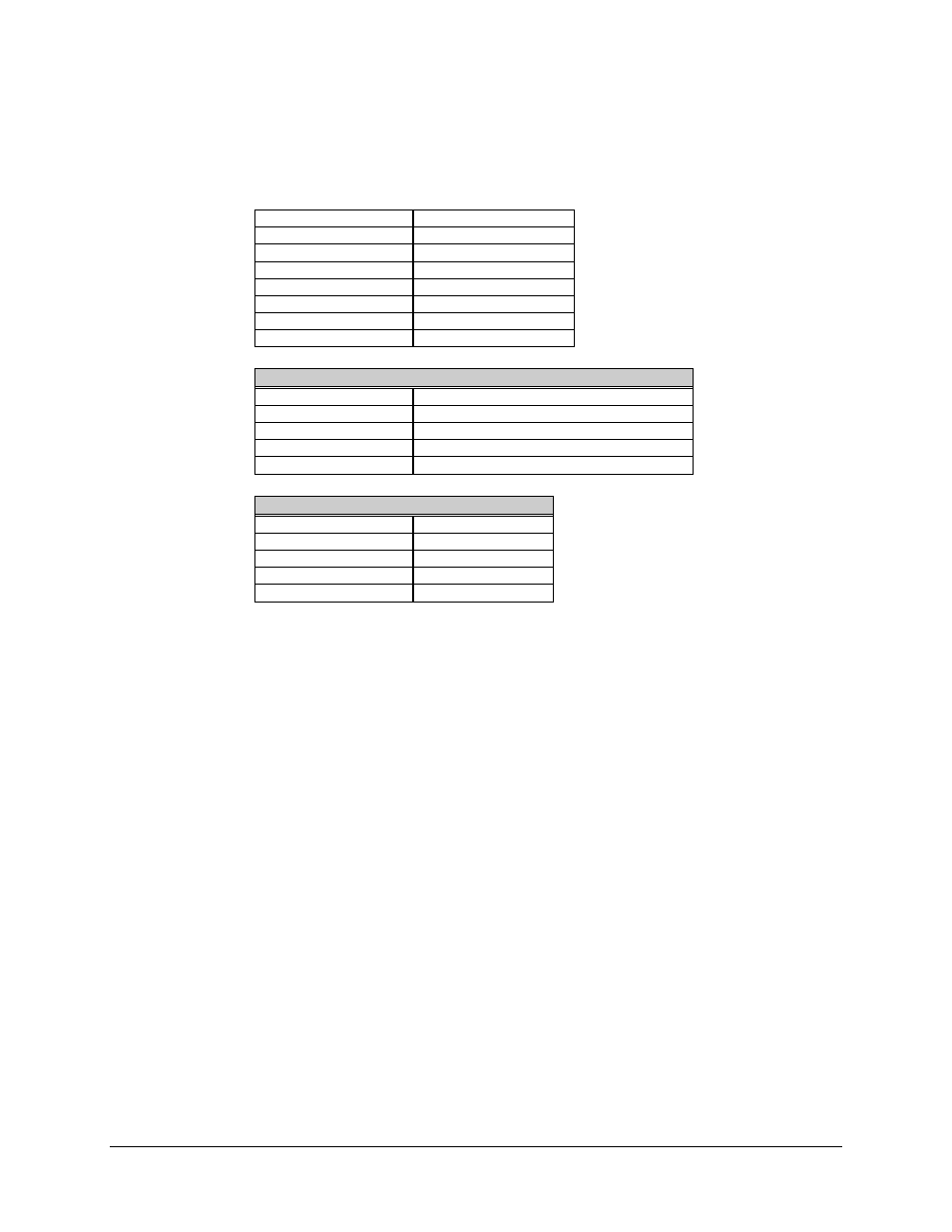
5.5.1 Specifications
Input Frequency
3620 to 4200 MHz
Input Connector
SMA Female
Input Impedance
50
Ω
Input VSWR
1.5:1
Output Frequency
70 MHz (± 18 MHz)
Output Connector
SMA Female
Output VSWR
1.3:1
1 dB Compression
+17.5 dBm
1st IF Synthesizer Input
Frequency
4662.5 to 5242.5 MHz, in 125 kHz steps
Level
+8 dBm
Connector
SMA Female
Return Loss
14 dB
Impedance
50
Ω
2nd IF Local Oscillator Input
Frequency
1112.5 MHz
Level
+13 dBm
Connector
SMA Female
Return Loss
14 dB
Impedance
50
Ω
5.5.2 Theory of Operation
The RFT-505 down converter utilizes a dual conversion process to convert from an input
RF frequency band of 3620 to 4200 MHz, to an output baseband 70 MHz IF signal.
The first conversion requires a down converter synthesizer frequency input to mix with
the RF input.
The M&C board controls the frequency selection of the synthesizer.
The synthesizer output frequency band is from 4662.5 to 5242.5 MHz, in 125 kHz steps.
The output of the first mixing process is at a frequency of 1042.5 MHz. The 1042.5 MHz
output is applied to the second mixer, which mixes with an IF Local Oscillator frequency
input at 1112.5 MHz.
The output of the second mixer is the desired baseband 70 MHz IF signal.
The M&C board interpolates the factory preset compensation data that is stored in an
EEPROM inside the down converter. This data allows the M&C board to command and
compensate the down converter’s output power, ensuring proper output power levels
over the entire frequency and temperature range.