Lx-bus™ operation, 1 description, 2 xr2500f on-board lx-bus – DMP Electronics XR2500F User Manual
Page 16: 3 lx-bus 481 zone expansion interface card, 4 installing the 481 card, Description, Xr2500f on-board lx-bus, Lx-bus 481 zone expansion interface card, Installing the 481 card, Introduction
Digital Monitoring Products
XR2500F Installation Guide
8
IntRoduCtIon
LX-Bus™ Operation
6.1 Description
The XR2500F Command Processor™ panel supports LX-Bus operation directly from the panel. Each LX-Bus
circuit provides 100 additional zones. Use J22 LX-Bus Header for the first 100 zones. Use the installed 481
Zone Expansion Interface Card for the next 100 zones. This provides a total of 200 expansion zones. To
install up to four additional Interface Cards use a Model 461 Interface Adaptor Card.
6.2 XR2500F On-board LX-Bus
To enable J22 to operate as an LX-Bus, place a jumper on the two pins next to the letter “L” on the J23
6-Pin header. When using J22 as an LX-Bus, connect a DMP Model 300 4-wire Harness to the J22 4-pin
header labeled LX-BUS. This provides the first 100 LX-Bus zones numbered 500-599. Respect wire colors
when connecting devices and use all four wires. Reset the panel using the J16 jumper to activate LX-Bus
operation. See Connecting LX-Bus and Keypad Devices section for maximum wiring distances.
Note: Do NOT use shielded wire when using the LX-Bus. Do NOT connect the wires from the 4-wire harness
to the panel terminals.
6.3 LX-Bus 481 Zone Expansion Interface Card
The 481 Zone Expansion Interface Card provides an additional 100 zones to the XR2500F. When used in
conjunction with the on-board J22 LX-Bus the 481 LX-Bus zones are numbered 600 to 699.
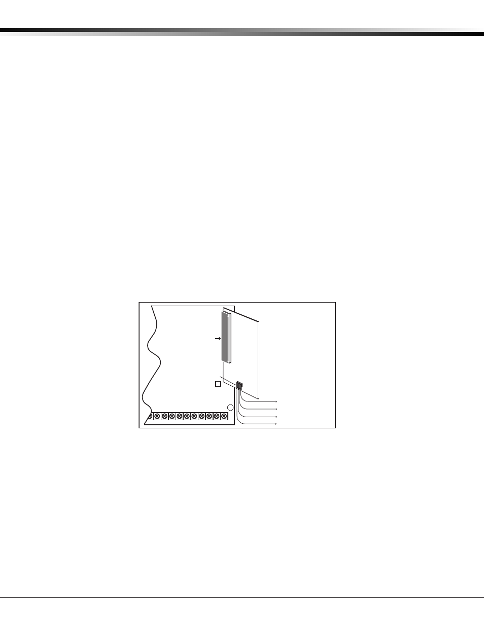
6.4 Installing the 481 Card
Remove AC and battery power from the XR2500F panel and ground yourself before handling and
installing the 481 Card.
1. Align the 481 Card 50 pin connector with the XR2500F panel J6 connector.
2. Press the 481 onto the J6 connector while applying even pressure to both sides.
B
J6 Interface Card
Connector
18
19
20
21
22
23
24
25
26
27
28
Z5
Z6
Z7
Z8
Z9+ Z9- Z10+ Z10-
GND
GND
481 Zone
Expansion
Interface
Card
Red—Auxiliary Power
Yellow—Data In
Green—Data Out
Black—Ground
Zone Expansion
Harness Connectors
To LX-Bus Modules
Command Processor
Panel
Figure 6: 481 Wiring