5 troubleshooting, 1 general, 2 led indications – Bronkhorst EL-FLOW Base 2014 User Manual
Page 31: 3 troubleshooting summary general, Hc , h c
BRONKHORST HIGH-TECH
5 Troubleshooting
5.1
General
For a correct analysis of the proper operation of a flow/pressure meter or controller it is recommended
to remove the unit from the process line and check it without applying fluid supply pressure. In case the
unit is dirty, this can be ascertained immediately by loosening the compression type couplings and, if
applicable the flange on the inlet side.
Energizing or de-energizing of the instrument of the instrument indicates whether there is an electronic
failure.
After that, fluid pressure is to be applied in order to check behaviour.
If there should be suspicion of leakage in case of a gas unit, do not check for bubbles with a leak
detection liquid under the cover as this may lead to a short-circuit in the sensor or p.c.board.
5.2
LED indications
The two LEDs on the instrument give information about the status of the instrument. Check chapter 3.6,
“LED indications” for detailed info.
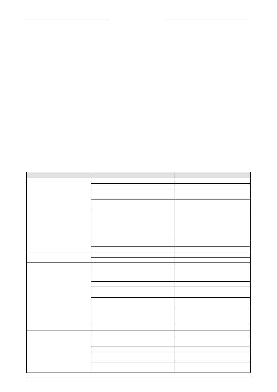
5.3
Troubleshooting summary general
Symptom
Possible cause
Action
No output signal
No power supply
1a) check power supply
1b) check cable connection
Output stage blown-up due to long lasting
shortage and/or high-voltage peaks
1c) return to factory
Supply pressure too high, or differential
pressure across meter too high
1d) lower supply pressure
Valve blocked/contaminated
1e) connect 0 .. 15 Vdc to valve and
slowly increase voltage while supply
pressure is ‘on’. The valve should open at
7V ± 3V; if not open, then cleaning parts
and adjust valve (qualified personnel
only)
Screen in inlet fitting blocked
1f) clean screen
Sensor/capillary failure
1g) return to factory
Maximum output signal
Output stage blown-up
2a) return to factory
Sensor/capillary failure
2b) return to factory
Output signal much lower than
setpoint signal or desired flow
Screen blocked/contaminated
3a) clean screen
LFD blocked/contaminated and/or liquid in
meter
3b) remove LFD and clean; dry meter
with air or
2
N
Valve blocked/contaminated
3c) clean valve
Valve internal damage (swollen seat in
plunger)
3d) replace plunger assembly and adjust
valve or return
Incorrect type of gas is used and/or
pressure/diff. pressure
3e) try instrument on conditions for
which it was designed
Flow is gradually decreasing
Condensation, occurs with
3
NH
,
hydrocarbons such as
10
4
8
3
H
C
,
H
C
etc.
4a) decrease supply pressure and/or heat
gas to be measured
Valve adjustment has changed
4b) see ‘1e’
Oscillation
Supply pressure/diff. pressure too high
5a) lower pressure
Pipeline too short between pressure regulator
and MFC
5b) increase length or diameter of piping
upstream
Pressure regulator is oscillating
5c) replace pressure regulator or try ‘5b’
Valve sleeve or internals damaged
5d) replace damaged parts and adjust
valve, see ‘1e’ or return to factory
Controller adjustment wrong
5e) adjust controller
9.17.061
EL-FLOW Base Series Mass Flow Controllers
Page 31