Optional equipment – Avalon Firestyles DVL Fireplace-1999 to 2002 User Manual
Page 52
5 0
Optional Equipment
(for qualified installers only)
Travis Industries
4 0 2 0 8 1 2
9 3 5 0 8 1 1 0
Thermostat (Part # 99300650)
!
Do not connect 120 VAC to the gas control valve or wiring of this unit.
+
It is easiest to route the remote control wire prior to installing the appliance. Route the wire to a
location near the gas inlet. Allow 3' of wire for hookup inside the heater.
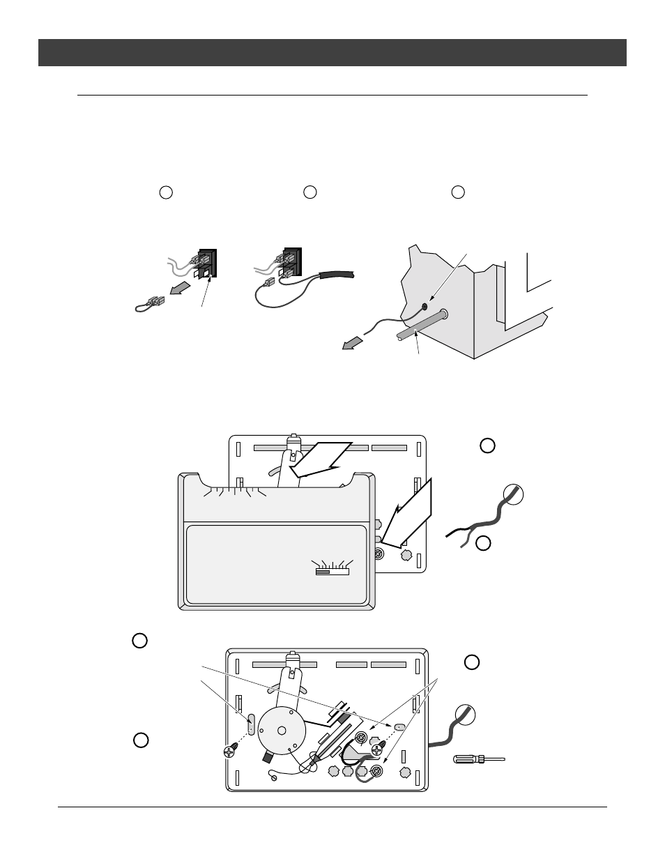
1
Attach the thermostat wire and route through the gas inlet hole (see the illustration below). Pull
through all the slack (you may wish to wrap the wire in electrical tape to prevent damaging the wire).
Remove the jumper wire on
the back of the on/off switch
and discard.
Back of
on/off switch
Red & brown wires
leading to the gas
control valve.
a
b
Connect the thermostat wires to back
of the on/off switch (orientation does
not matter).
c
Route the thermostat wire out the grommet-lined
thermostat hole (located behind the hole for the
gas line on either side).
Jumper Wire
(green wire)
Thermostat Wire
Hole (with grommet)
Gas Line
2
Determine a location for the thermostat that is within range of the 50' length of thermostat wire. It
should be centralized in the room and away from the heater. The wire may be routed externally on the
wall or behind the wall (preferred).
3
Follow the directions below to install the thermostat.
50 60 70 80 90
50 60 70 80 90
Robertshaw
Run the thermostat wires
through the wall (cut off excess
wire, leaving 6” of slack).
Pull the cover off the thermostat
Expose 1/2” of wire and
attach to these two posts.
Standard
Screwdriver
Attach the thermostat to
the wall through these
two holes.
a
b
c
d
Re-attach the cover
removed in step “a”.
e