Avalon Firestyles B-Vent-1995 User Manual
Page 8
P
AGE
8
S
TOVE
I
NSTALLATION
(
CONT
.) -
For qualified installers only!
3
Direct the two red wires for the on/off switch and the molex connector for the blower out the back
right of the heater (there are also two red wires leading to the spill switch Ð leave these wires in place).
4
Place the top panel upside down against a non-scratching surface. Attach the two strips of gasket
along the outside of the two studs on each side. Attach each side panel to the top panel with two 10-
32 lock-washer hex nuts (the smaller of the hex nuts) Ð use a 3/8" nutdriver. Do not over-tighten.
Attach each forward mounting bracket with two 10-32 nuts - use a 3/8" nutdriver.
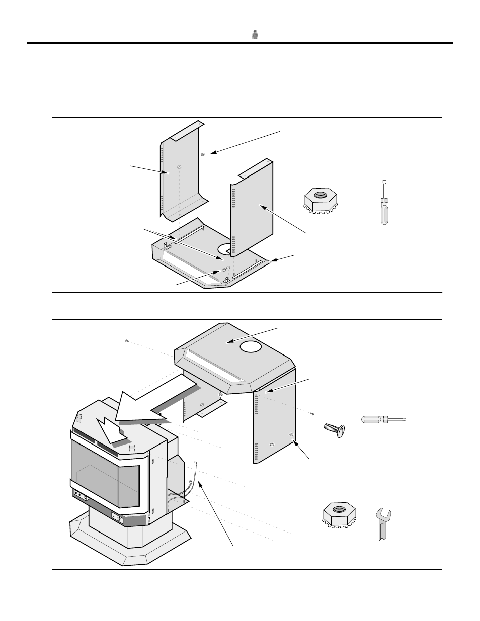
Lay the top panel on a non-scratching
surface upside down. Attach the side
panels to the top panel with the four 10-32
hex nuts (the smaller of the two sizes)
until the gasket compresses.
Apply the two 6" long
gaskets along the
outside of the studs
Left side panel
Right side panel
Attach each Forward Mounting
Brackets with two 10-32 nuts.
Top panel
3/8" Nutdriver
5
Slide the side and top panels onto the heater from the back. Make sure the wires do not get caught
under the side panels. Attach with the four 1/4-20 lock-washer hex nuts and two screws.
Slide the top and side panels into place,
making sure they go underneath the wires
and gas line.
7/16" Wrench
Route the on/off switch and blower
wires to the right rear of the heater.
Attach the side panels to the heater
with four1/4-20 hex nuts (reach in
from the rear of the heater with a
7/16" wrench to tighten).
Attach the forward brackets of
the top panel to the heater with
the two black screws.
Standard
Screwdriver