Nsert, Nstallation, Installation preparation – Avalon Firestyles B-Vent-1995 User Manual
Page 16: Items packed with the heater, Items packed with the insert panel kit, Items packed with the insert shell kit, Order of installation, Installing the gas inlet
P
AGE
16
I
NSERT
I
NSTALLATION
-
For qualified installers only!
Installation Preparation
!
This appliance must be installed in accordance with all local codes, if any; if not, follow
ANSI Z223.1 and the requirements listed in this manual. Failure to follow all of the
requirements may result in property damage, bodily injury, or even death.
!
Notify your insurance company before hooking up this heater.
!
The requirements listed below are divided into sections. All requirements must be met
simultaneously. The order of installation is not rigid Ð the qualified installer should follow
the procedure best suited for the installation.
Items Packed with the Heater
¥
Avanti Gas Heater (with Faceplate)
¥
On/Off Switch (with jumper wire attached)
¥
Log Set (2 Logs, 2 Twigs, Ember Strip)
¥
Owner's Manual
¥
2 Gas Inlet Pipes (the shorter one is for inserts)
Items Packed with the Insert Panel Kit
¥
Top, Left, and Right Surround Panels
¥
Trim Kit (3 pieces trim, 2 "L" brackets, set screws, double-back tape)
¥
Two Leveling Bolts
Items Packed with the Insert Shell Kit
¥
Upper Top ¥
Control Cover ¥ Hardware Kit
Order of Installation
1
Install the gas inlet
(8-3/4" length of 3/8" pipe)
2
Position the heater (see the section "Heater
Placement")
3
Connect the gas line. Connect the gas vent.
4
Install the logs and test the heater (see the
instructions under "Finalizing the Installation")
5
Install the insert panel kit.
6
Install the insert shell kit.
7
Follow the instructions under "Finalizing the
Installation" on pages 23 through 27.
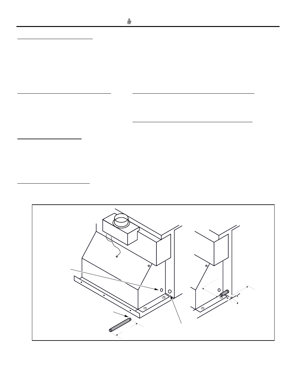
Installing the Gas Inlet
¥
Locate the 8-3/4" gas inlet pipe included with the heater (the longer one may be discared). Apply
thread sealant to one end and insert it through the rear of the insert into the 90
°
elbow on the gas
control valve. Tighten with a pipe wrench.
Back of
Heater
Gas Inlet
(3/8" diameter pipe)
8-3/4"
NOTE:
Apply thread sealant
prior to installing.
NOTE:
If you wish to
route the blower
outlet to the left
side of the
heater, the power
cord may
removed from the
right side and
routed through
this hole (see the
instructions on
the following
page).
Insert the gas inlet through this hole and into
the elbow directly off the gas control valve.
NOTE:
With the insert in
place, the gas line
center is located 4-
5/8" back from the
fireplace opening,
1-1/2" above the
hearth, and 10-
3/8" from the
center of the
insert.
!
Leak check all gas line connections.