Pressure sensor voltage chart – Auto-Zone Control Systems Auto-Zone Basic Systems Installation & Operation (Version 02C) User Manual
Page 142
Section 4
Auto-Zone Basic
4-40
Start-Up and Troubleshooting
Pressure Sensor Voltage Chart
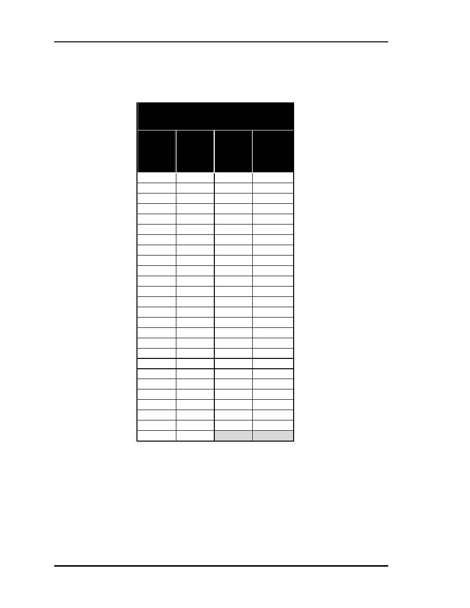
Table 4-3: Pressure Sensor Voltage
OE271 Duct Static
Pressure Sensor
Pressure
@
Sensor
(“ W.C.)
Voltage
@
Input
(VDC)
Pressure
@
Sensor
(“ W.C.)
Voltage
@
Input
(VDC)
0.00 0.25 2.60 2.20
0.10 0.33 2.70 2.28
0.20 0.40 2.80 2.35
0.30 0.48 2.90 2.43
0.40 0.55 3.00 2.50
0.50 0.63 3.10 2.58
0.60 0.70 3.20 2.65
0.70 0.78 3.30 2.73
0.80 0.85 3.40 2.80
0.90 0.93 3.50 2.88
1.00 1.00 3.60 2.95
1.10 1.08 3.70 3.03
1.20 1.15 3.80 3.10
1.30 1.23 3.90 3.18
1.40 1.30 4.00 3.25
1.50 1.38 4.10 3.33
1.60 1.45 4.20 3.40
1.70 1.53 4.30 3.48
1.80 1.60 4.40 3.55
1.90 1.68 4.50 3.63
2.00 1.75 4.60 3.70
2.10 1.83 4.70 3.78
2.20 1.90 4.80 3.85
2.30 1.98 4.90 3.93
2.40 2.05 5.00 4.00
2.50 2.13
Notes:
1. Use the voltage column to check the Duct Static Pressure Sensor while connected to powered
controllers. Read voltage with meter set on DC volts. Place the “-” (minus) lead on the GND ter-
minal and the “+” (plus) lead on the
SIG terminal on TB1.