Zone controller, Step 1, Auto-zone basic – Auto-Zone Control Systems Auto-Zone Basic Systems Installation & Operation (Version 02C) User Manual
Page 137
Auto-Zone Basic
Section
4
Start-Up & Troubleshooting
4-35
Zone Controller
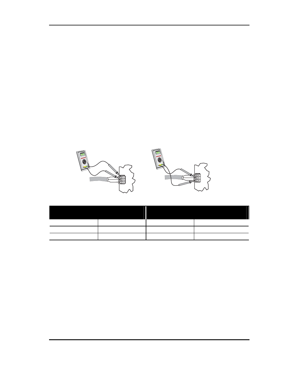
Test the communications loop with the system powered. Set meter to read DC Volts.
These tests assume that if the optional CommLink is installed, it is also connected and
powered up. Actual meter readings may deviate slightly depending on the number of
zones installed. Any significant deviation from these values generally indicates a prob-
lem.
If voltages are not within specified ranges, one of the Zone Controller communications
driver chips is likely damaged and will have to be replaced.
Step 1
Measure the voltage at one of the Zone Controller terminals with the Communications
Loop connected to the Zone Controller. If you can communicate with some zone control-
lers on the loop but not others, start with the first Zone Controller you can’t communicate
with to begin testing.
Basic System - Without Optional
CommLink Installed
Basic System - With Optional
CommLink Installed
Measure Voltage Measure Voltage
T to SHLD
+ 2.7 to 2.4 VDC
T to SHLD
+ 3.1 to 2.9 VDC
R to SHLD
+ 2.6 to 2.3 VDC
R to SHLD
+ 2.1 to 1.9 VDC
If the voltages are within the specified voltage ranges, the Zone Controller and communi-
cations loop are operating within specifications. If the measured voltages are not within
the specified voltage ranges, proceed to Step 2.
T
SHLD
R
COMM
LOOP
+
-
T
R
SHLD
+
-
T
SHLD
R
COMM
LOOP
+
-
T
R
SHLD
+
-
Measuring R to SHLD
Measuring T to SHLD