Step 2, Auto-zone basic, 36 start-up and troubleshooting – Auto-Zone Control Systems Auto-Zone Basic Systems Installation & Operation (Version 02C) User Manual
Page 138
Section 4
Auto-Zone Basic
4-36
Start-Up and Troubleshooting
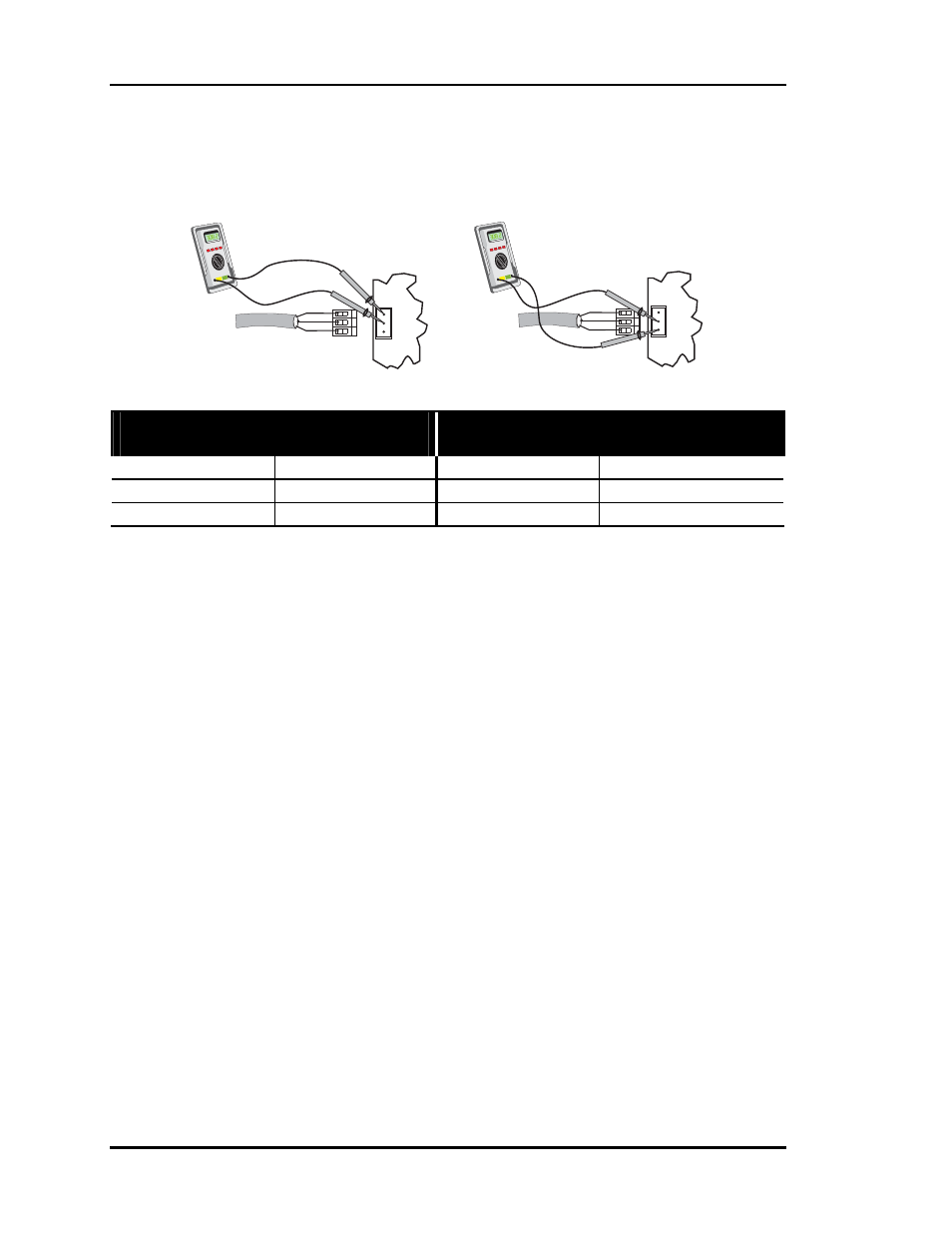
Step 2
Measure the voltage at the suspect Zone Controller terminals with the Communications
Loop disconnected form the Zone Controller.
Basic System - Without Optional
CommLink Installed
Basic System - With Optional
CommLink Installed
Measure Voltage Measure Voltage
T to SHLD
+ 2.5 to 2.4 VDC
T to SHLD
+ 2.5 to 2.4 VDC
R to SHLD
+ 2.5 to 2.4 VDC
R to SHLD
+ 2.5 to 2.4 VDC
If the voltages are not within the specified voltage ranges, the Zone Controller communi-
cation driver chip is probably damaged and will require replacement. If the measured
voltages are within the specified voltage range, the Zone Controller driver chip is not
damaged and the problem is related to another part of the loop. Repeat Zone Controller
troubleshooting Steps 1 & 2 for each controller on the loop to determine which one is
causing the problem. If you have a CommLink (optional) installed, please see the
CommLink Troubleshooting Section of this manual.
T
SHLD
R
COMM
LOOP
+
-
T
R
SHLD
+
-
T
SHLD
R
COMM
LOOP
+
-
T
R
SHLD
+
-
Measuring R to SHLD
Measuring T to SHLD