Zone manager wiring, Auto-zone basic, Rockerd own – Auto-Zone Control Systems Auto-Zone Basic Systems Installation & Operation (Version 02C) User Manual
Page 111: Basic zone manager, Warning, Belimo
Auto-Zone Basic
Section
4
Start-Up & Troubleshooting
4-9
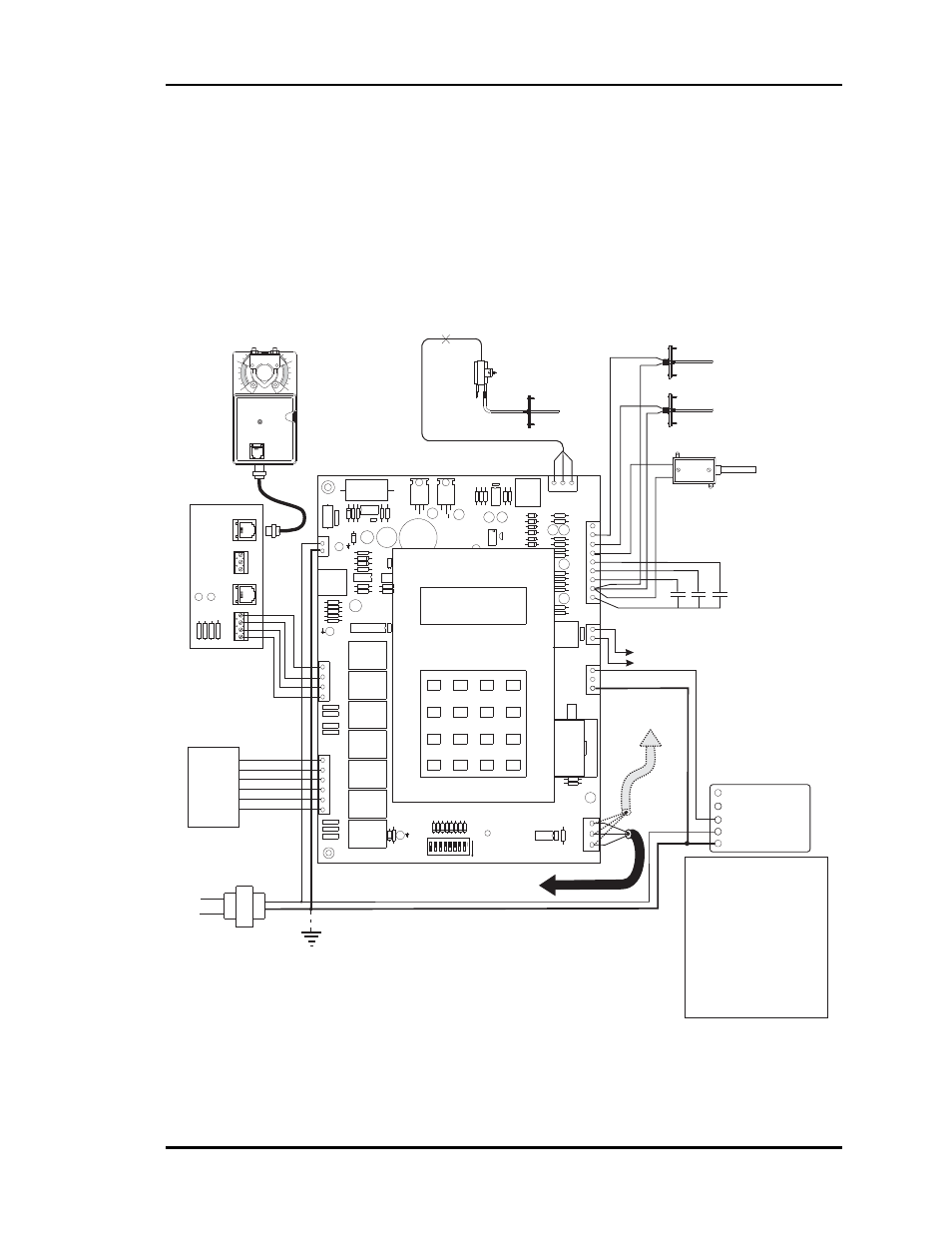
Zone Manager Wiring
Correct wiring of the Zone Manager is critical to proper system operation. If components
are wired to the wrong inputs, the system will not operate correctly or will not operate at
all. Correct wiring of the 24VAC power is extremely critical. If voltage greater than
24VAC is applied to the terminal, it will damage the board beyond repair. All 24VAC
wiring must be connected so that all ground wires remain common. Failure to comply
with this will also result in damage to the board. See Figure 4-7. Also see Section 2 of
this manual for more detailed wiring instructions and procedures.
Figure 4-7: Zone Manager Wiring
Basic Zone Manager
Notes:
1.)24 VAC Must Be Connected So
That All Ground Wires Remain
Common.
3.)All Communication Wiring To Be 18
Ga. Minimum, 2 Conductor Twisted
Pair With Shield. Belden #82760 Or
Equivalent.
2.)All Wiring To Be In Accordance With
Local And National Electrical Codes
and Specifications.
RS-485
Communications
To CommLink
When Used
RS-485
Communications To Zone
Controllers
Return Air Temp.
Sensor
Suppy Air Temp.
Sensor
Line
Voltage
HV
AC
Unit
24VAC Only
Red
Blk
To Relief / Exhaust Fans
Grn
Static
Pick-up
Static
Pressure
Sensor
Splice As
Required
LO
HI
GND
24VAC
Belimo Actuator Wiring Shown.
Consult Factory For Other
Models Of Economizer Actuators.
Some Actuators Require Isolation
Transformers In Order To Prevent
Damage To The Controller Board.
WARNING!
Use Extreme Care When Wiring
Economizer Actuators
Never Connect Or Disconnect
Wiring With Power Applied!
Never Apply Power If The
Gnd ( 1 Com ) Terminal On The
Actuator Is Not Connected.
See Note 1 &2
Outdoor Air Temp.
Sensor
(See Note 4)
Aux3
Forced
Occupied
Mode
Aux1
Economizer
Disable
Aux2
Filter
Alarm
Auxiliary Inputs
( Dry Contacts )
R
G
Y1
Y2
W1
W2
Economizer Actuator
133 IN-LB
AF24-SR
1 COM
2 +
3 Y1
4 Y2
5 U
BELIMO
C
9
8
7
CABLE
R6
R5
HEAT 2
SW1
W2
W1
Y2
HEAT2
HEAT1
COOL2
COOL1
FAN
HEAT 1
COOL 2
COOL 1
C 1992
1
16
32
B
NET
2
4
8
ADD
COMM DRIVER
RS-485
75176
MADE IN U.S.A.
D17
D18
D19
D20
D21
D22
D23
D24
0
*
#
D
R
SH
T
COMM
C1
C2
+
P1
RIBBON
GND
G
Y1
V6
V5
CLOSE
V4
V3
OPEN
GND
FDBK
FAN
CLOSE
OPEN
+
REC
+
GND
NE5090
4
5
6
KEYPAD
1
2
3
B
A
LCD DISPLAY
&
+
+
24VAC
TB2
POWER
+
+
+
ADJUST
5.11V
PJ1
+
+
PRESSURE
SENSOR
JACK
+5V
SIG
BUSS
EXP
TB2
A2
G
OUTPUTS
ANALOG
A1
N.O.
CONTACTS
EXHAUST
AUX3
GND
GND
AUX2
AUX1
ANALOG
SAT
OAT
RAT
INPUTS
+12V
TB12
BYPASS
BYPASS
Local Loop
OFF
>
RockerD
own
Bypass & Slave
Interface Card
Bypass
Air Damper
Actuator
1
0
FROM
ZONE
CONTROLLER
BYP
ASS
AND
SLA
VE
INTERF
ACE
YS101824
T
O
ACTUA
TO
R
OPEN
CLOSE
FDBK
OPEN
GND
GND
PJ1
PJ2
LD2
LD1
OPEN
CLOSE
CLOSE
TB1
TB2