Components & wiring, Zone manager io & components, Auto-zone basic – Auto-Zone Control Systems Auto-Zone Basic Systems Installation & Operation (Version 02C) User Manual
Page 110: 8 start-up and troubleshooting
Section 4
Auto-Zone Basic
4-8
Start-Up and Troubleshooting
Components & Wiring
The following information is intended as a review of the procedures and design data pro-
vided in Section 2 of this manual. Section 2 should be thoroughly studied before attempt-
ing the initial installation of the system. If, however, you find yourself starting up or trou-
bleshooting a system that was installed by someone else, the following information
should be helpful in gaining a quick overview of the system you are working with.
Zone Manager IO & Components
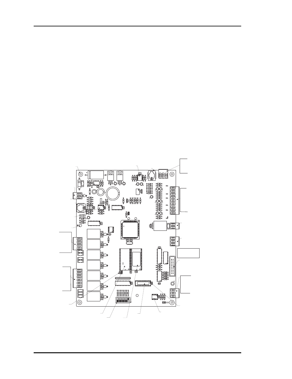
The Zone Manager inputs, outputs, and components are shown below. It is important to
familiarize yourself with these components and their locations to facilitate proper
connection, startup, and troubleshooting of the Basic System. See Figure 4-6.
Figure 4-6: Zone Manager Components
U13
CX13
EPROM
U11
CX11
U10
RAM
CX10
JO2
32K
8K
16
32
2
8
4
ADD
1
NET
B
V9
V8
V7
R
FAN
COOL1
COOL2
HEAT1
HEAT2
K8
K7
K6
K5
K4
K3
K2
CLOSE
OPEN
GND
FDBK
V4
V3
V6
V5
TB7
R57
HEAT2
D31
HEAT1
D22
R56
D21
R52
COOL2
COOL1
R46
D20
FAN
D19
R44
CLOSE
D18
OPEN
D17
R43
R41
D23
D24
D26
D25
D29
D30
D28
D27
SW1
U14
CX14
MADE IN U.S.A.
1992
RN2
1
R58
U15
CX15
R59
R60
RS-485
COMM DRIVER
T
SH
R
U12
CX12
R49
R55
R45
R47
R48
C22
COMM
P1
CX9
U9
ANALOG
OUTPUTS
EXP
BUSS
ECONOMIZER
EXH/RELIEF
GND
TB8
TB5
YS101722
Rev. 2
C21
C20
X2
R42
D16
EXHAUST
CONTACTS
N.O.
TB4
V2
C6
U2
R7
R38
R37
C15
C16
R31
R30
R28
R27
R19
C13
C14
R14
R17
R16
R12
C7
C8
R11
TB3
GND
GND
AUX2
AUX3
SAT
RAT
OAT
AUX1
+12V
ANALOG
INPUTS
D2
D3
D5
D4
D8
D6
R15
C11
U7
CX7
Q2
PJ1
+5V
SIG
GND
PRESSURE
SENSOR
JACK
TB1
R5
R4
R2
R3
R1
U1
CX1
C4
C5
D1
R9
C1
C2
C3
VR2
VR1
SC1
24VAC
V1
R10
U3
CX3
U5
CX5
Q1
R22
R21
D10
R23
R24
R20
R36
R29
R33
R35
R32
R34
CX4
C12
R25
D12
VR3
R13
R26
D11
D9
R18
U6
CX6
C17
D13
D14
D15
R39
R40
I2C EXP PORT
GND
TB2
POWER
D7
L1
C9
Y1
EWDOG
J01
U8
C18
C19
5.11V
ADJ
5.11V
ADJUST
PU1
PU2
PU3
PU4
PU5
PU6
RN1
REC
BYPASSPDAMPER
R61
HVAC Unit
Connections
(R) Common
Fan
Cool 1
Cool 2
Heat 1
Heat 2
Bypass
Damper
Connections
FDBK
GND
Open
Close
RS-485
Communications
Loop Connection
T
SH
R
Typical
Pin 1
Indicator
RAM
Chip
EPROM
Chip
PAL
Chip
RAM Size
Select
Jumper
RS-485
Communications
Driver Chip
Real Time
Clock Chip
Real Time
Clock Chip
Display &
Keypad
Ribbon Cable
Connector
Static Pressure
Sensor Inputs
+5V
SIG
GND
Static Pressure
Sensor - Optional
Modular Connection
Input
Comm
LED
Not Used
Address Switch
(Set To 0 Without
CommLink. Set to 17
With CommLink)
Analog Inputs
SAT
RAT
OAT
AUX1
AUX2
AUX3
GND
Analog Output
0-10 VDC
Economizer
Binary Output
Relief/Exhaust
Fans
Power LED
24 VAC
Power Input
Mounting Holes
Typ. Of 4
Note:
Keypad & Display
Not Shown