10 ddr3 sdram, 11 gpio, 10 ddr3 sdram 7.11 gpio – Artesyn COMX-P40x0 ENP2 Installation and Use (January 2015) User Manual
Page 106: Table 7-4, Gpio states
BSP
COMX-P40x0 ENP2 Installation and Use (6806800R95C)
106
7.10 DDR3 SDRAM
The COMX-P4080 module has two fully programmable DDR3 SDRAM controllers. A maximum
of 2 GB SDRAM are mapped in U-Boot. If more than 2 GB SDRAM is fitted, the remaining
sections are left unmapped. With Linux, up to 4 GB SDRAM can be verified.
Do not modify the contents of the lowest 1 MB and the top 1 MB RAM in the U-Boot. Both areas
are used to store critical data by U-Boot.
When the U-Boot detects the DDR3 SDRAM during boot up, the following message appears:
7.11 GPIO
The COMX-P40x0-ENP2 module has 20 general purpose input/output (GPIO), 12 connected to
the CPU, and 8 implemented on an I2C expander. For more information, see
DRAM: Initializing...
2 GB left unmapped
DDR: 4 GB (DDR3, 64-bit, CL=9, ECC on)
DDR Controller Interleaving Mode: cache line
DDR Chip-Select Interleaving Mode: CS0+CS1
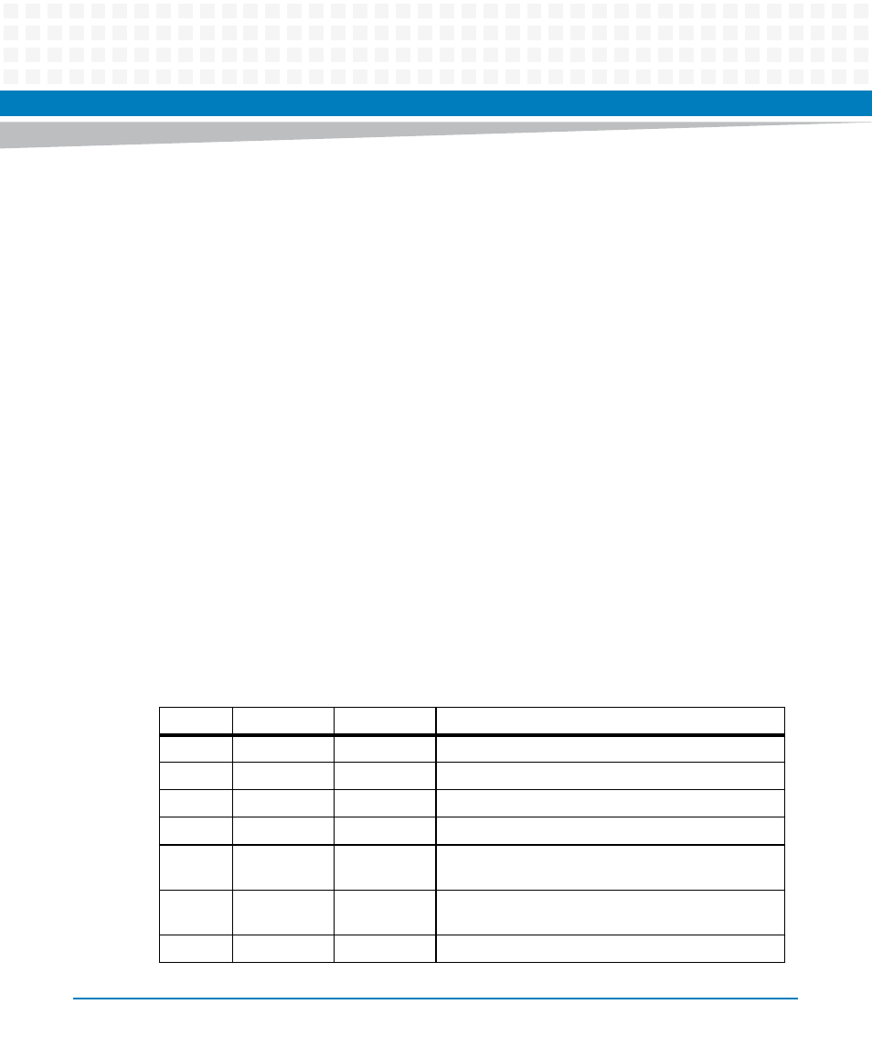
Table 7-4 GPIO States
GPIO#
Input/Output
Reset State
Description
GPIO00
I
I
GPI0 of COM-E connectors
GPIO01
I
I
GPI1 of COM-E connectors
GPIO02
I
I
GPI3 of COM-E connectors
GPIO03
I
I
GPI4 of COM-E connectors
GPIO04
O
I
GPO0 of COM-E connectors and also as to control
debug LED D18
GPIO05
O
I
GPO1 of COM-E connectors and also as to control
debug LED D19
GPIO06
O
I
GPO3 of COM-E connectors