Table 4-5, Selecting rcw sources between nor and nand flash, Table 4-6 – Artesyn COMX-P4080 Installation and Use (August 2014) User Manual
Page 61: Rcw hard-coded configuration options, Functional description
Functional Description
COMX-P4080 COM Express Module Installation and Use (6806800L20C)
61
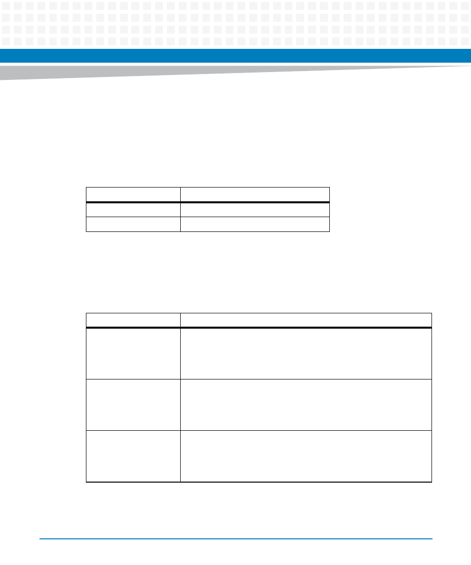
The "X" on the table indicates the "ON" or "OFF" state of the corresponding bits of the S2 switch.
Both NOR and NAND flash are attached to the local bus of the COMX-P4080. The chip select
signal (CS) of the selected RCW source should be connected to the CS0 of the local bus. When
set by the fifth bit of the S1 switch, neither the NOR or NAND flash can be selected as the RCW
without properly setting the S1.5.
In cases where all the devices fail to work, hardware strapping can be picked as an option for
loading the RCW. This is also useful for quick debugging purposes. The hard-code
configuration details are shown the table below.
Table 4-5 Selecting RCW Sources Between NOR and NAND Flash
S1.5
RCW Source
ON
CS0 attached to NAND flash
OFF (Default)
CS0 attached to NOR flash
Table 4-6 RCW Hard-Coded Configuration Options
S2.1-S2.5
RCW hard-code configuration options
ON,ON,ON,OFF,ON
Large page NAND flash as boot location;
USB2 and dual 4-pin UART enabled;
Platform ratio of 8:1;
Core PLL ratio of 14:1
ON,ON,ON,OFF,OFF
Large page NAND flash as boot location;
RGMII FM1 MAC1 and dual 4-pin UART enabled;
Platform ratio of 8:1;
Core PLL ratio of 14:1
ON,ON,ON,ON,ON
16-bit NOR flash as boot location;
USB2 and dual 4-pin UART enabled;
Platform ratio of 8:1;
Core PLL ratio of 14:1