3 calibration, Table 5–2. potentiometer adjustment procedures -3, Figure 5–1. potentiometer locations -3 – AMETEK DLM Series User Manual
Page 73
DLM-E 3kW & 4kW Series Power Supplies
Maintenance and Troubleshooting
5.3 Calibration
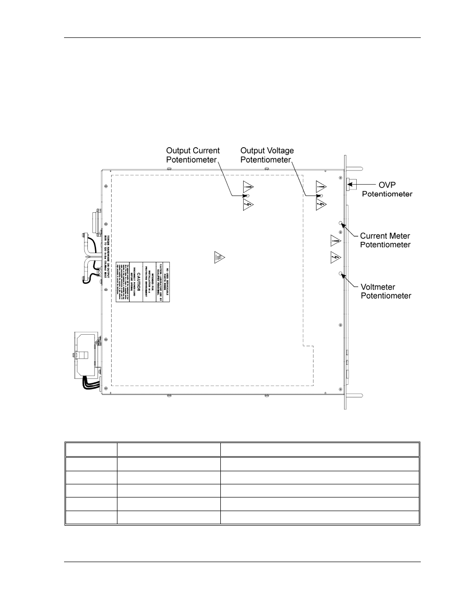
Calibration of the output voltage, current, or OVP is accomplished using multiturn trimpots.
Table 5–2 gives the location, function, and effect of each potentiometer.
Calibration is performed at the factory during testing. Recalibration should be performed
annually and following major repairs. With the cover in place, calibration should be done
through access holes in the cover or front panel. See Figure 5–1.
Figure 5–1. Potentiometer Locations
Location
Function
Adjustment Procedure
Top Cover
Output Voltage
Clockwise rotation increases output voltage setting
Top Cover
Output Current
Clockwise rotation increases output current setting
Top Cover
Front Panel Voltmeter
Clockwise rotation increases voltage meter reading
Top Cover
Front Panel Current Meter Clockwise rotation increases current meter reading
Front Panel OVP
Clockwise rotation increases OVP shutdown setting
Table 5–2. Potentiometer Adjustment Procedures
M362000-01 Rev E
5-3