3 shutdown application – contact closure, Shutdown application – contact closure -18 – AMETEK DLM Series User Manual
Page 62
Advanced Operation
DLM-E 3kW & 4kW Series Power Supplies
Figure 4–12. Using Shutdown with a DC Input (Positive Logic)
4.5.3
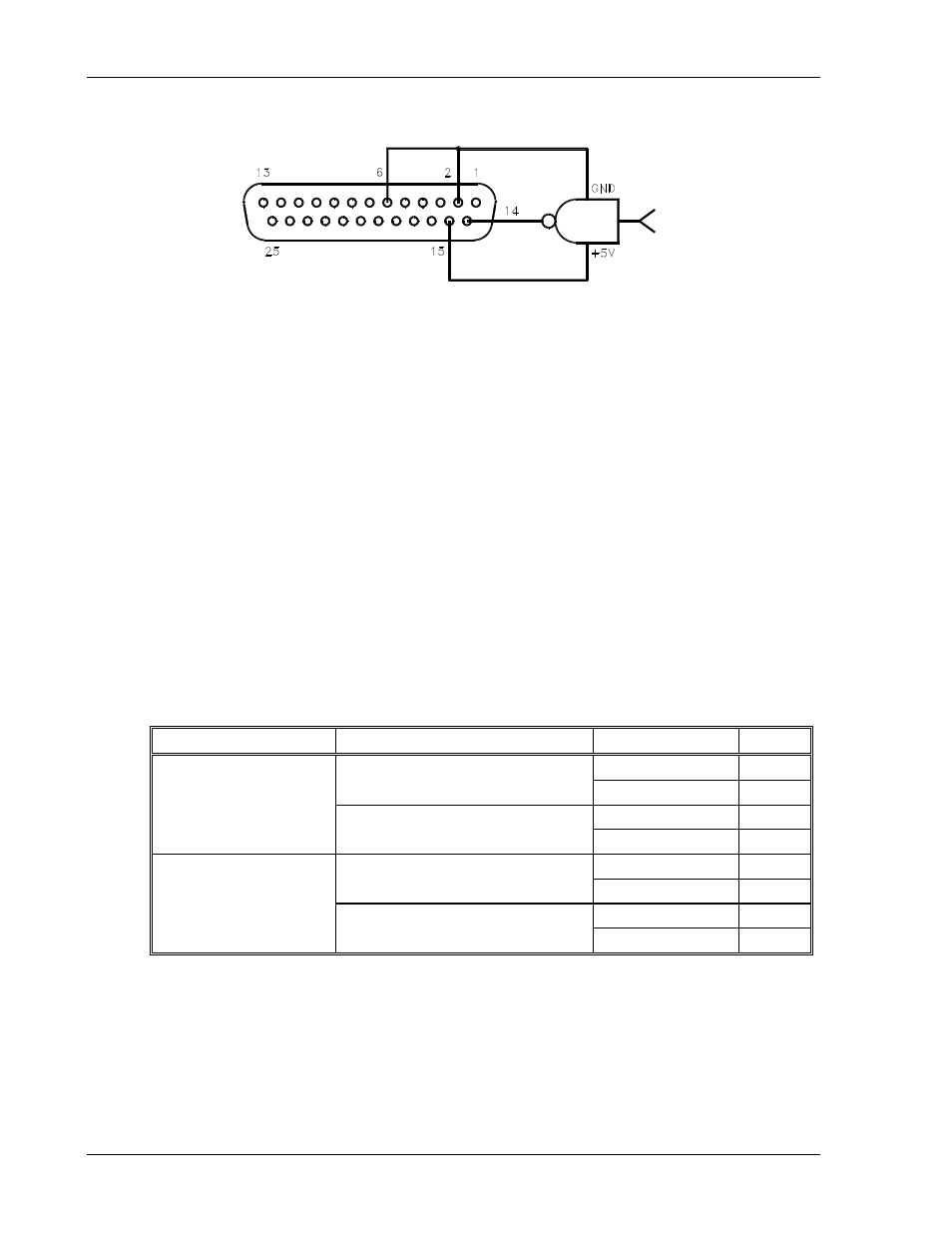
Shutdown Application – Contact Closure
An external relay, whether normally open or normally closed, may be used to activate the
Shutdown circuit. Either positive or negative logic may be used.
To activate the Shutdown function using an external relay:
1. Turn off the power supply.
2. Connect one side of the external relay to pin 15 (+5 VDC Auxiliary Output) on connector
J3. Connect the other side of the relay to J3-pin 14 (Remote Shutdown Input). Also
connect pin 2 (Shutdown Return) to pin 6 (Status Indicator Return). See Figure 4–13
through Figure 4–16.
3. Set rear panel DIP switch S1 to select the desired circuit logic as defined in the following
table.
Relay
Switch S1-6 Setting
Relay Coil State Output
Normally Open Relay
UP–Open (Positive Logic)
Energized OFF
De-energized ON
DOWN–Closed (Negative Logic)
Energized ON
De-energized OFF
Normally Closed Relay
UP–Open (Positive Logic)
Energized ON
De-energized OFF
DOWN–Closed (Negative Logic)
Energized OFF
De-energized ON
The red S/D (Shutdown) LED on the front panel lights up when the Shutdown circuit is
activated.
4-18
M362000-01 Rev E