2 programming output voltage, Programming output voltage -8 – AMETEK DLM Series User Manual
Page 52
Advanced Operation
DLM-E 3kW & 4kW Series Power Supplies
4.3.2
Programming Output Voltage
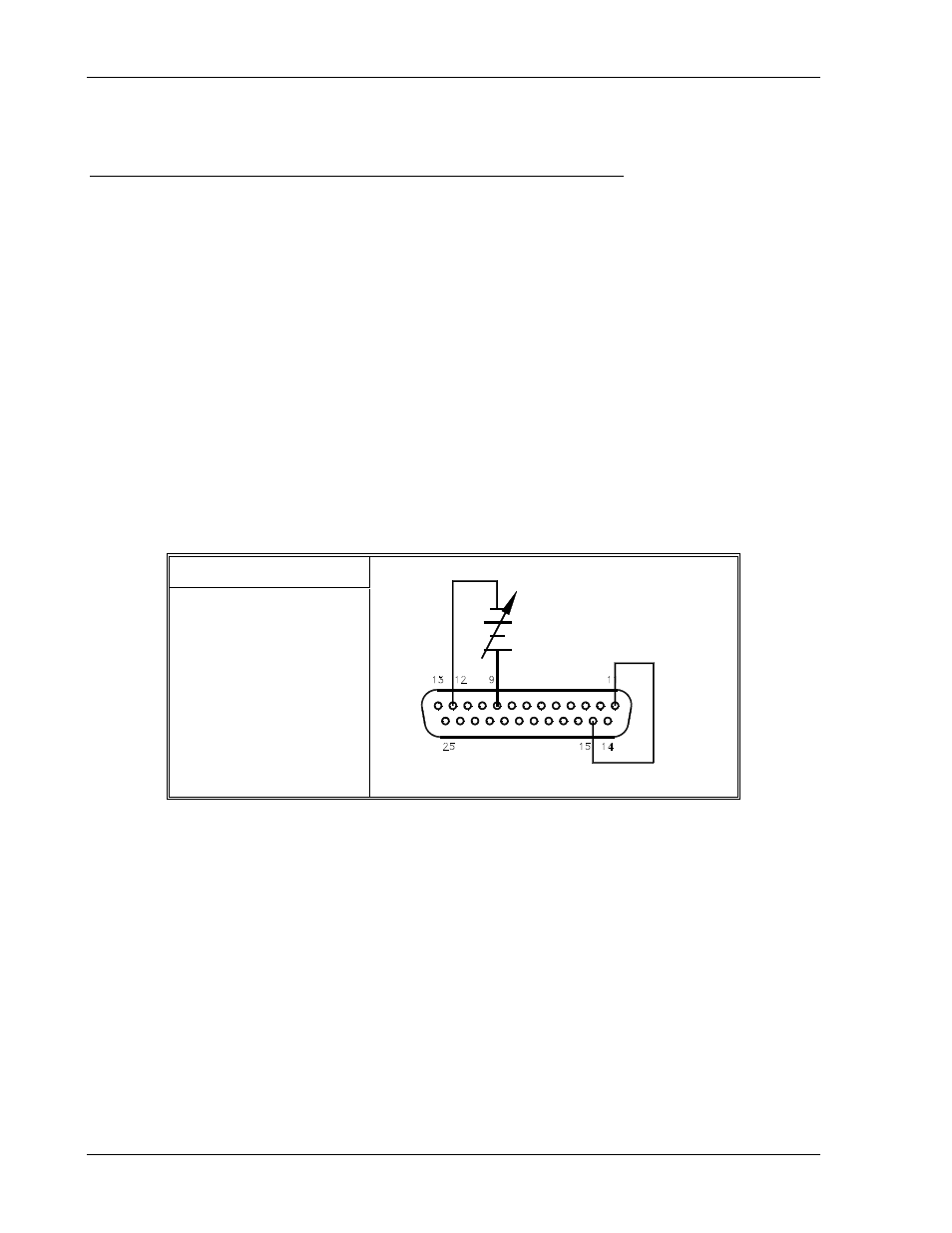
Programming Output Voltage with a 0–5 VDC or 0–10 VDC Source
1. Set S1-1, the rear panel DIP Switch, UP, in the open position for 0–5 VDC programming
range.
2. Set S1-1, the rear panel DIP Switch, DOWN, in the closed position for 0–10 VDC
programming range.
3. Connect the external programming source between pins 9 (voltage programming
input/positive) and 12 (return). Varying the programming voltage from 0 to maximum will
cause the output to vary from 0 to 100% of the model rating. Adjust the programming
signal to zero.
4. Turn the power supply ON.
5. Set the front panel LOCAL/REMOTE switch to the REMOTE position and adjust the
external programming source voltage. By pressing the V&I PREVIEW button and
observing the front panel voltmeter reading, the external control can be adjusted to the
desired setting.
S1 Switch Settings
S1-1 OPEN = 0–5V
S1-1 CLOSED = 0–10V
Figure 4–4. Programming Output Voltage with a 0–5 VDC or 0–10 VDC Source
4-8
M362000-01 Rev E