Figure 3–3. j11 sense connector -5 – AMETEK DLM Series User Manual
Page 43
DLM-E 3kW & 4kW Series Power Supplies
Basic Operation
5. The optimal point for the shield ground must be determined by experiment, but the most
common connection point is at the power supply's return output connection at the load.
6. Turn the power supply ON.
Notes:
1. If the power supply is operated with remote sense lines connected and with either of the
positive or negative load lines not connected, the power supply shutdown circuit will be
activated, causing the output voltage and current to fall to zero.
2. If the power supply is operated without remote sense lines or local sense jumpers in
place, the supply will continue to work, but supply regulation will be degraded and/or
erratic.
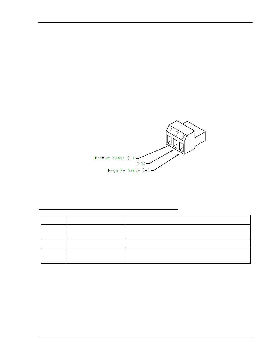
Figure 3–3. J11 Sense Connector
Rear Panel J11 Sense Connector Terminals and Functions
Terminal Name
Function
J11-1
Positive Sense (+SNS)
Remote positive sense connection.
Default connection to (+) bus bar or output connector.
J11-2 N/C
No
connection.
J11-3
Return Sense (–SNS)
Remote negative sense connection.
Default connection to (–) bus bar or output connector.
M362000-01 Rev E
3-5