AMETEK DLM Series User Manual
Page 53
DLM-E 3kW & 4kW Series Power Supplies
Advanced Operation
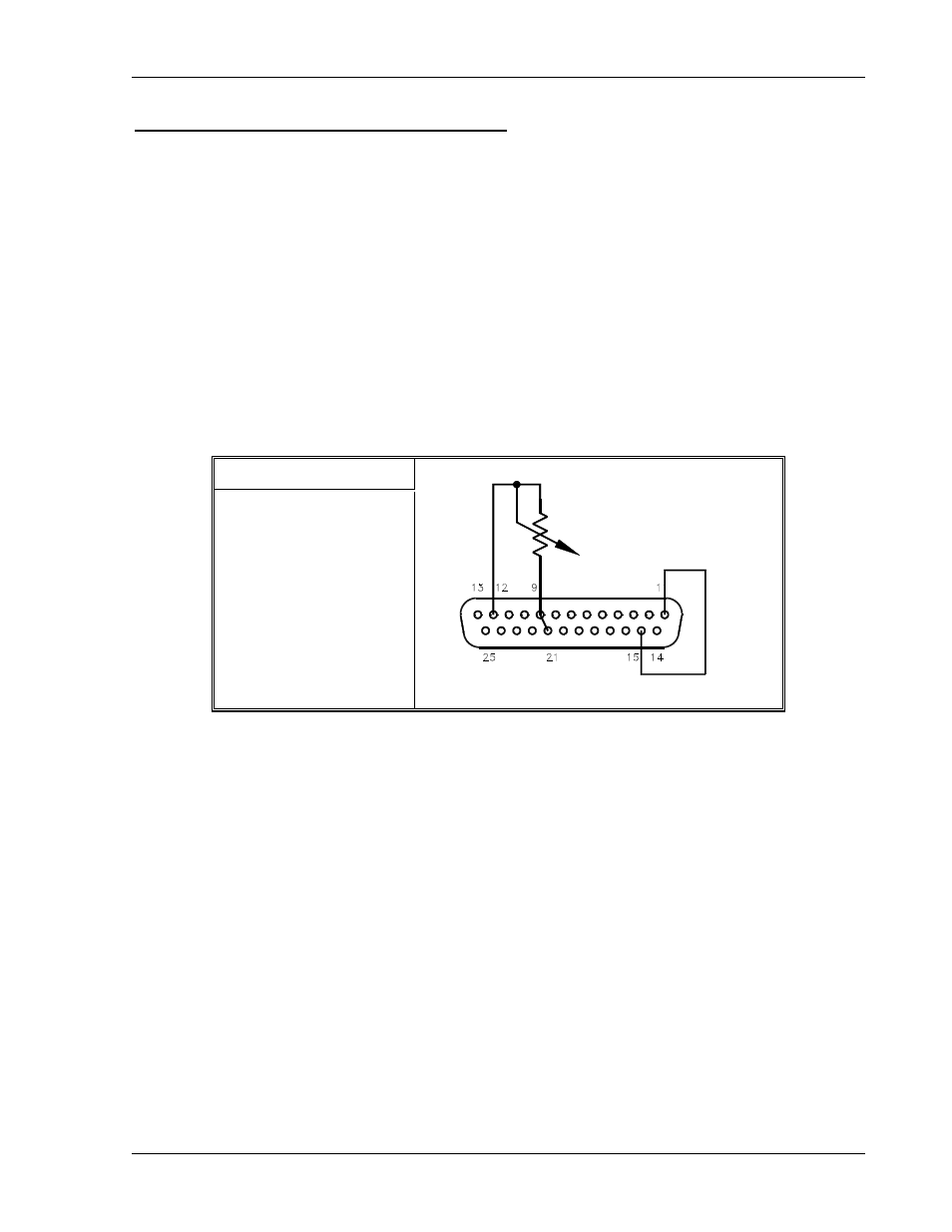
Programming Output Voltage with Resistance
1. Set S1-1, the rear panel DIP Switch, UP, in the open position for 0–5k ohm programming
range.
2. Connect pins 9 (voltage programming input/positive) and 21 (1mA current source for
voltage control) to the counter–clockwise end of the potentiometer and connect the tap
and clockwise end of the potentiometer to pin 12 (return). Adjusting the resistance from
0 to maximum will vary the output voltage from 0 to 100% of the model rating. Adjust the
programming signal to zero.
3. Turn the power supply ON.
4. Set the front panel LOCAL/REMOTE switch to the REMOTE position and adjust the
external programming resistance. By pressing the V&I PREVIEW button and observing
the front panel voltmeter reading, the external control can be adjusted to the desired
setting.
S1 Switch Settings
S1-1 OPEN = 0–5K
Figure 4–5. Programming Output Voltage with a 0–5k Ohm Resistance
M362000-01 Rev E
4-9
- CW-M (48 pages)
- CW-M Corrected Table 4-2 in (1 page)
- CW-P (62 pages)
- Lx Series (205 pages)
- CW Series Programming Manual (25 pages)
- Ls Series II Programming Manual (242 pages)
- Compact i/iX Series (157 pages)
- Compact IX 2253 (157 pages)
- Compact i/iX Series Software Manual (203 pages)
- ASD Series Quick Start (5 pages)
- ASD Series (120 pages)
- i-iX Series II Programming Manual (226 pages)
- DLM 600W Series Programming Manual (24 pages)
- M131 Programming Manual (99 pages)
- DLM 600W Series (82 pages)
- BPS Series (153 pages)
- DLM600 Series (16 pages)
- DCS-E 1.2kW Series (65 pages)
- DLM-E 4kW Series Programming Manual (32 pages)
- M136 (8 pages)
- DCS-E 3kW Series (94 pages)
- CTS 3.0 (166 pages)
- CSW Series (174 pages)
- 2003RP (126 pages)
- 2001RP (131 pages)
- MX CTSH (151 pages)
- MXCTSL Administrator Manual (27 pages)
- MX CTSL (157 pages)
- RS Series (228 pages)
- MX Series Installation Manual (35 pages)
- Ls AC source (2 pages)
- MX15 Series (184 pages)
- Ls Series II (226 pages)
- Lx Series Driver Manual (275 pages)
- MX Series Rev: AY (257 pages)
- iX Series (341 pages)
- i-iX Series II (258 pages)
- GUPS 2400A-108 (36 pages)
- HPD Series (58 pages)
- HPD Series Operation Manual (41 pages)
- HPD Series GPIB-Multichannel (134 pages)
- PLA-PLW Programming Manual (74 pages)
- ReFlex Mating Connnectors for Controller (3 pages)
- LPDC-16V (4 pages)