2 status indicators, 7 using multiple supplies, 2 status – AMETEK DLM Series User Manual
Page 65: Indicators, Using multiple supplies -21
DLM-E 3kW & 4kW Series Power Supplies
Advanced Operation
4.6.2
Status Indicators
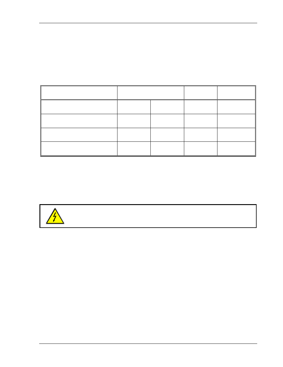
Status indicators for thermal shutdown, OVP circuit, programming mode, and operating mode
are available via connections on the J3 connector on the rear panel.
The following table shows the indicator signals, the J3 connector pin at which they are
available, an approximation of the signal magnitude, and the source impedance through which
the signal is fed. Use 20 to 24 AWG wiring.
Indicator Signal /
Alternate State
J3 Connections
Signal (+) Return (–)
Signal
Voltage
Source
Impedance
Overtemperature Shutdown /
Normal Operation
Pin 18
Pin 18
Pin 6
Pin 6
+5V
0V
1k ohms
1k ohms
OVP Circuit Activated /
OVP Circuit Not Activated
Pin 17
Pin 17
Pin 6
Pin 6
+5V
0V
1k ohms
1k ohms
Remote Programming Mode /
Local Programming Mode
Pin 4
Pin 4
Pin 6
Pin 6
+5V
0V
1k ohms
1k ohms
Voltage Mode Operation /
Current Mode Operation
Pin 5
Pin 5
Pin 6
Pin 6
+5V
0V
1k ohms
1k ohms
4.7 Using Multiple Supplies
DLM–E Series power supplies of the SAME MODEL may be operated with outputs in series or
in parallel to obtain increased load voltage or increased current. Split supply operation allows
two positive or a positive and a negative output to be obtained. The power supply output may be
biased up to a maximum of 150 VDC with respect to the chassis.
WARNING!
Use extreme caution when biasing the output relative to the chassis due to
potentially high voltage levels at the output and J3 terminals.
Do not attempt to bias program/monitor signal lines on the J3 connector relative to the power
supplies positive output. The signal returns on the J3 program/monitor connector are at the
same potential as the power supply return bus bar in a standard unit. Using the Isolated
Programming Interface option allows control from a programming source biased relative to the
supply’s output. Contact factory for additional details.
4.7.1
Configuring Multiple Supplies for Series Operation
Series operation will obtain a higher voltage from a single output using two or more supplies.
Connect the negative (–) output terminal of one supply to the positive (+) output terminal of the
next supply. See Figure 4–17. The total voltage available is the sum of the maximum voltages of
each supply (add voltmeter readings). The maximum allowable current for a series string of
power supplies is the model rated output current of a single supply in the string.
Note: The maximum allowable sum of the output voltages is 300 VDC. This is limited by the
voltage rating of certain internal components. See Section 1 for maximum voltage rating.
M362000-01 Rev E
4-21