AMETEK DLM Series User Manual
Page 57
DLM-E 3kW & 4kW Series Power Supplies
Advanced Operation
Remote Programming of the Current Limit Only
CAUTION!
Always remove J3 mating connector from supply before soldering.
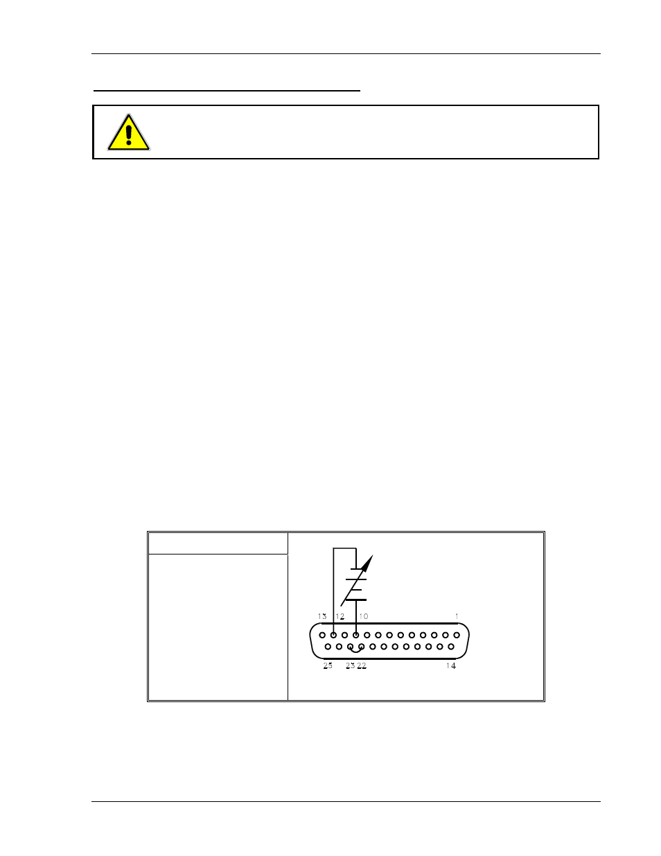
For remote programming of current limit only:
1. Turn off power to the supply.
2. Connect a programming source between pins 10 (current limit programming
input/positive) and 12 (return).
3. Connect a jumper between remote programming connector pins J3-22 and J3-23 for
external control of the current limit.
4. Adjust the external programming signal to zero.
5. Switch the ENABLE/STANDBY switch to STANDBY.
6. Turn the power supply ON.
7. Set the front panel LOCAL/REMOTE switch to the LOCAL position and adjust the
external programming signal. By pressing the V&I PREVIEW button and observing the
front panel ammeter reading, the external control can be adjusted to the desired setting.
8. Adjust the voltage and OVP controls to the desired settings with the front panel controls.
9. Switch the ENABLE/STANDBY switch to ENABLE.
10. The current limit setting is now remotely programmed with local control of the output
voltage and OVP settings.
S1 Switch Settings
S1-2 OPEN = 0–5V
S1-2 CLOSED = 0–10V
Figure 4–9. Programming Output Current Remotely, Local Control of Voltage Limit/OVP
M362000-01 Rev E
4-13