3 resetting rear panel dip switch settings, 4 making j3 connections, Resetting rear panel dip switch settings -4 – AMETEK DLM Series User Manual
Page 48: Making j3 connections -4
Advanced Operation
DLM-E 3kW & 4kW Series Power Supplies
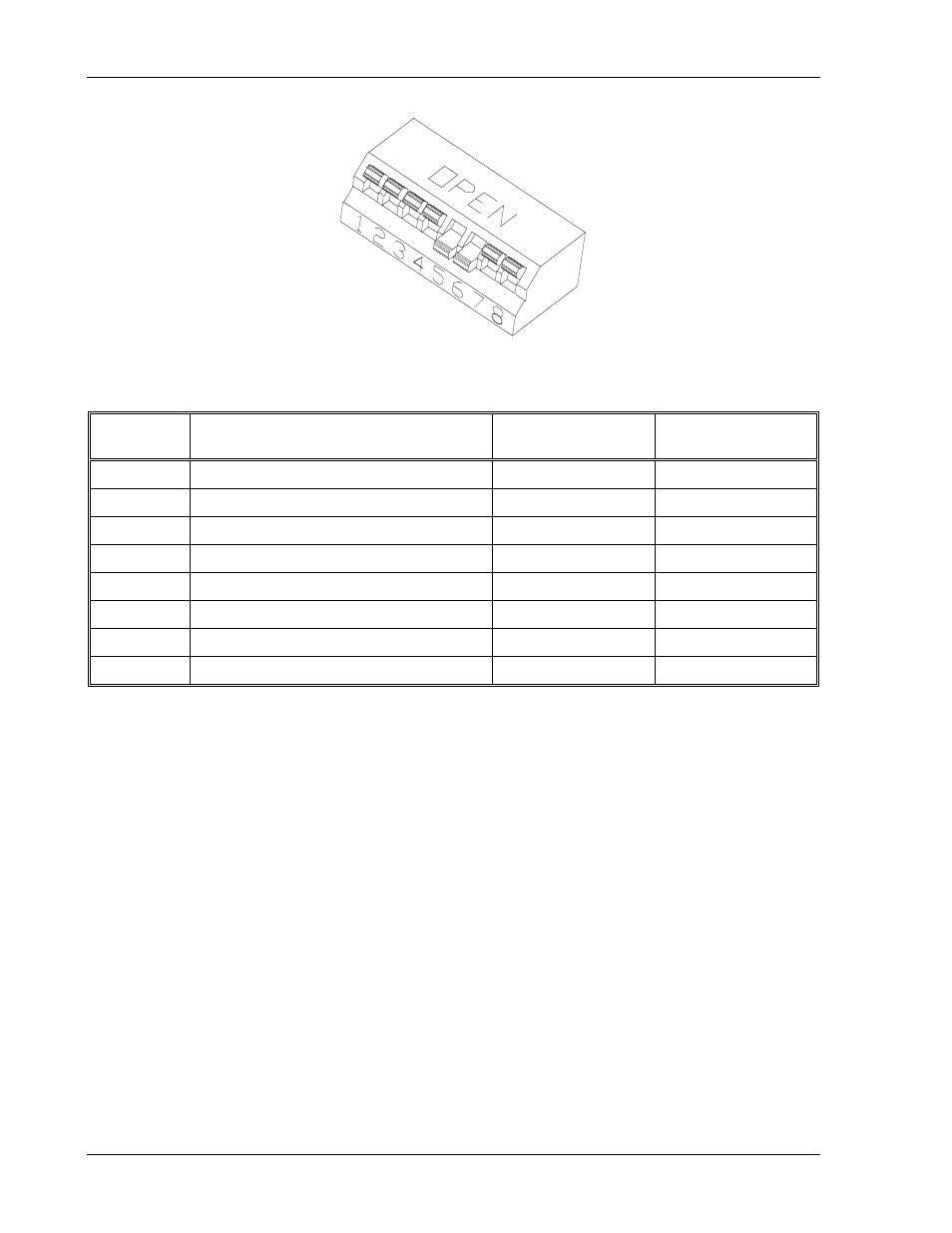
Figure 4–2. Locating Jumpers, Switch, and Connector
Switch
Position
Function
Open Position
(Up) *
Closed Position
(Down)
S1-1
Voltage Programming Input Range
0–5 VDC
0–10 VDC
S1-2
Current Programming Input Range
0–5 VDC
0–10 VDC
S1-3
OVP Programming Input Range
0–5 VDC
0–10 VDC
S1-4
Voltage Monitor Output Range
0–5 VDC
0–10 VDC
S1-5
Current Monitor Output Range
0–5 VDC
0–10 VDC
S1-6
Remote Shutdown Activation
Active High Signal
Active Low Signal
S1-7
Master/Slave Parallel Output Enable
Single or Master
Slave
S1-8
Front Panel Lockout
Normal
Lockout Mode
* Factory default position
Table 4–2. Rear Panel S1 DIP Switch Functions and Settings
4.2.3
Resetting Rear Panel DIP Switch Settings
Some applications require the default factory settings of the rear panel 8–position DIP switch,
S1. If the switch requires resetting, read Section 2.2, and follow the procedures in this section.
Always turn off the front panel power switch before moving any DIP switch settings.
4.2.4
Making J3 Connections
The default factory configuration of the J3 connector has no jumpers. Other applications will
require placing pin–to–pin connections or making connections to external devices such as
voltage sources, or resistances. Read Section 2.2 Safety, and follow the procedures in this
section whenever the rear panel connector, J3, is to be reconfigured. Always turn off the front
panel power switch before soldering to the J3 connector, and only solder with the mating
connector removed from the supply.
4-4
M362000-01 Rev E