Table 4–3 for parallel port connector function and – AMETEK DLM Series User Manual
Page 68
Advanced Operation
DLM-E 3kW & 4kW Series Power Supplies
4.7.3
Configuring Multiple Supplies for Parallel Operation
Parallel operation is used to obtain a higher current output supply using up to five units. The
DLM–E supplies are designed to be easily paralleled with current sharing between units with the
use of a simple cable between supplies. See Figure 4–20.
Notes:
1. Set the rear panel switch S1–7 down on the Slave unit(s) only. This allows for full
control of the output voltage, current, and OVP trip level through one Master supply.
2. To control the slaves, plug the Master/Slave cable into J12 of the Master supply and
into J13 of the first Slave supply.
3. Plug an identical cable into J12 on this slave and connect to J13 on any subsequent
Slave supplies as required until all supplies in the Master/Slave set have a cable
plugged into either J12 or J13 or both.
4. Ensure that all of the outputs of the positive terminals (+) and negative terminals (–)
are also connected in parallel. Refer to Section 2.8 for a discussion on the proper
method for connecting to the load.
5. The total current available is the sum of the maximum currents of each supply. Each
supply will read back the portion of current that it is supplying to the load and these
must be added together to get the total load current.
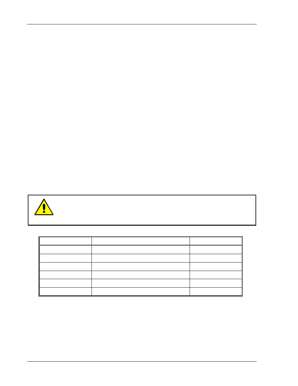
CAUTION!
To prevent internal damage, ensure that the Master/Slave Parallel Output
Enable switch S1–7 is Up on the Master supply and Down on all Slaves.
There can be only one Master supply!
Pin Number
Function
Voltage Level
1
Parallel OVP Control
0–5 V
2
Parallel Current Command
0–7V
3
Parallel Command Return (–)
0V
4
Parallel Voltage Control
0–5V
5
Parallel Output Command
5V
6
Programming/Monitor Return (–)
0V
Table 4–3. J12, J13 Connectors–Parallel Port Function and Pinout
4-24
M362000-01 Rev E