Figure 19. z51f0811 mcu configuration example – Zilog Z51F0811 User Manual
Page 28
UM024002-0512
The Z8051 On-Chip Debugger
Z8051 On-Chip Debugger and In-System Programmer
User Manual
20
including the PLL and ADC functions, will be stopped when selecting
Stopped concur-
rently
. The Peripheral Control menu selection is disabled (greyed out) in the Break/Con-
figure menu during emulation.
The Peripheral Control function does not control each peripheral individually.
Chip Configuration
The Chip Configuration function is used to configure the target MCU’s I/O pin function,
oscillation method, code protection, etc. Each device series features different configura-
tions. If a configuration changes, the user must turn off power to the target MCU, then
power it on again. As a result, configurations can be influenced when power rises to oper-
ational voltage.
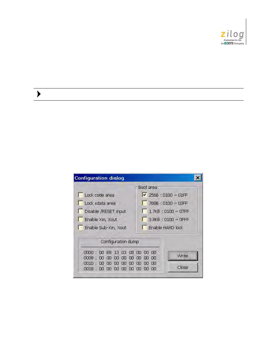
The Configuration dialog box shown in Figure 19 offers an example configuration for the
Z51F0811 device.
The Chip Configuration menu selection is disabled (greyed out) in the Break/Configure
menu during emulation.
Figure 19. Z51F0811 MCU Configuration Example
Note: