Indic – CIRCUTOR DISPENSER Series User Manual
Page 96
Long press the
button when the screen shown in
is displayed to open the general
display screens.
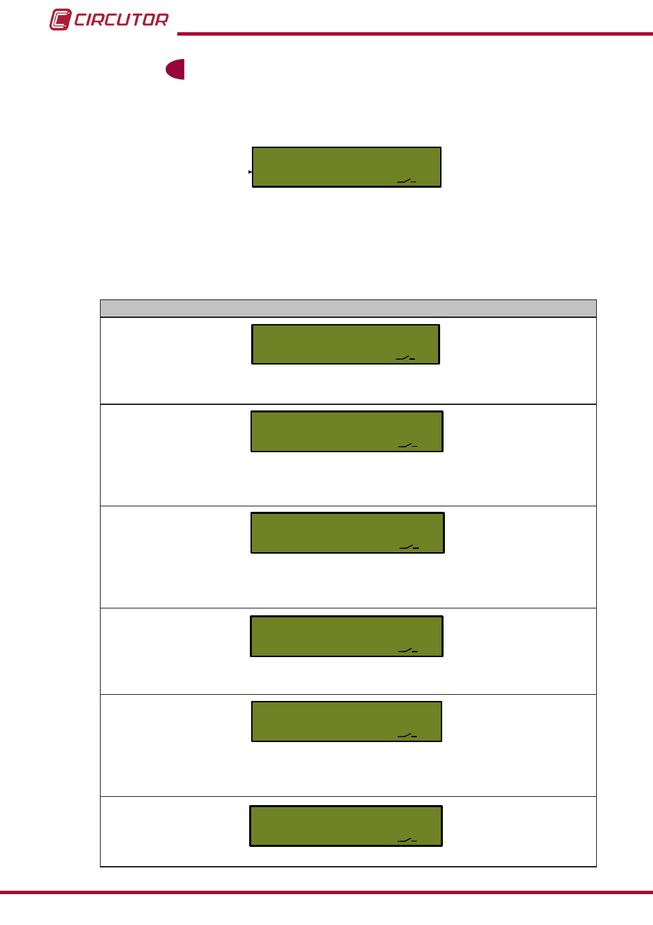
5�5�2�1�- OPERATION INDICATORS
indiC
L1
L40
Figure 108:Operation Indicators Menu�
This menu displays the information of the operation indicators. It is used for checking all the ba-
sic aspects of the correct operation of the unit during installation or in subsequent on-site tests.
Table 36: Operation indicator menu screens�
Screens
L1
1.13.38
0
Active quadrant, indicates the direction of active or reactive energy or the quadrant.
Range of values: 1, 2, 3, 4.
L1
1
1.12.38
Presence of voltage, indicates the presence of voltage in each phase.
Range of values: 1, Voltage in L1. 2, Voltage in L2
3, Voltage in L3. Blank, no voltage
L1
0
1.11.38
Direction of current, indicates the direction of the current in each phase.
Range of values ( L1, L2, L3): . 1, import 2, export.
0, no current.
L1
L1
1.18.128
1
Active contract tariff, indicates the tariff that is currently active when the contract
is read.
L1
L1
n
0.96.5.0
Alarms, indicates the alarms that have been activated in the unit.
Range of values: C, critical alarm. n, non-critical alarm
b, battery alarm.
L1
00.50
kW
0.135.0
Adjusted power limit
96
Dispenser Universal System
Instruction Manual