Modbus, Ontrol frame, Cpc3i-xrs – CIRCUTOR computer PLUS-TF Series User Manual
Page 66: 1 modbus control frame
66
Table 13-1.- Connection of CPC3i to Computer plus
The connection diagrams of the complete unit are shown on Fig. 2 and 3.
Each CPC3i card of a static capacitor bank must be configured with a different address (1 to 16) for each
step, using a rotating ADJ switch with the CPC3i card.
CPC3i-xMRS
Mando RS485
0
V
2
3
0
V
4
0
0
V
2
G
2
2
K
2
2
G
1
2
K
1
TR1
3
G
2
3
K
2
3
G
1
3
K
1
1
K
2
1
G
2
1
G
1
1
K
1
TP3
TP2
TP1
LED
PH3
LED
PH2
LED
PH1
S
H
R
S
+
R
S
-
A
L
1
C
O
M
JP1
LED
CPU
TEST
0
7
1
5
3
1
1
1
2
4
5
6
8
9
1
0
1
2
1
3
1
4
ADJ
A B C D E F G
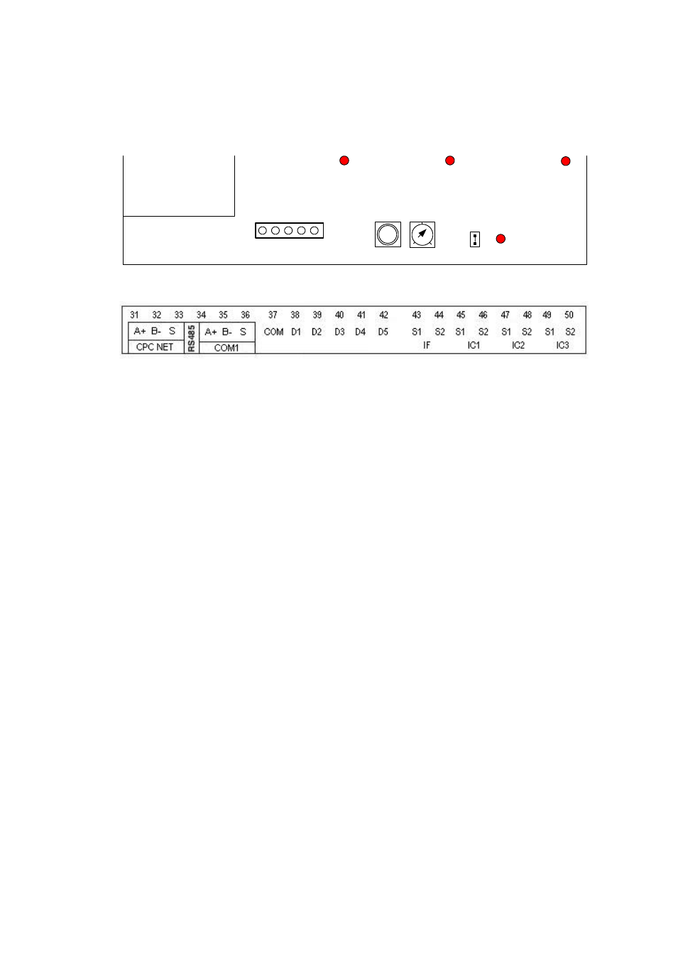
Fig. 121.- Terminals of the
CPC3i-xRS
card
Fig. 122.- Terminals of card A of Computer plus
13.1
MODBUS Control frame
Computer plus controls the CPC3i cards with the MODBUS protocol. In particular, it sends a frame every
20 ms, using the 15 function (N bits write). The message is a "broadcast" message, i.e., it will be read by all
cards, in any address. The format of the frame is as shown on Fig. 123.
The message is composed of a frame sent to the slave address 00H (broadcast, i.e., all CPC3i cards receive
all frames). The 1r bit address on the CPC3i card is 00H
– 64H and the frame has 64 bits (00H – 40H),
grouped in 8 octets.