Adjusting the transformer ratios – CIRCUTOR computer PLUS-TF Series User Manual
Page 40
40
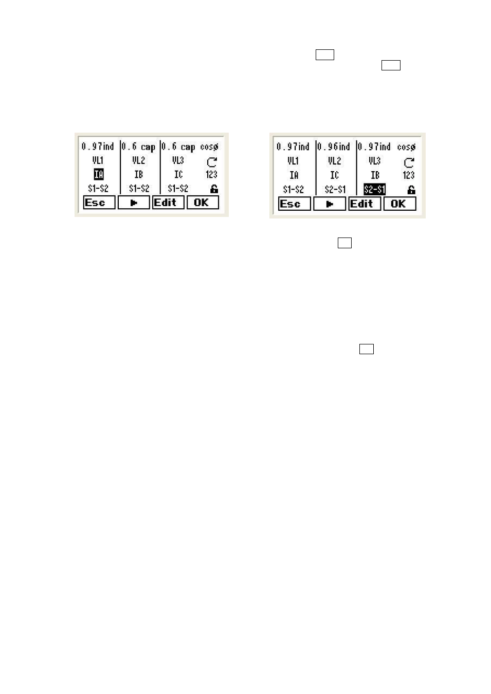
To edit the information on the screen shown on Fig.47, press the
Edit option and the screen shown on
Fig.48 will be displayed. Use the arrow to change the field being edited. Pressing
Edit again we may
change IB by IC, for example, or S1-S2 by S2-S1.
If you do not know how the cables of the current transformers (CTs) are connected, try various
combinations until you obtain a coherent cos
reading. Imagine this can be achieved with the setup
shown on Fig. 49. This would mean that the CT of phases 2 and 3 are changed and that the secondary
of phase 3 has S1-S2 inverted.
Fig. 48.- Menu to change CT connections
Fig. 49.- Menu to change CT connections
When the setup is producing a coherent set of cos
values, press
OK and adjust the transformer
connections.
7.3.6
Adjusting the transformer ratios
In this menu, the voltage transformer and the current transformer ratios can be adjusted. In general, there
will only be voltage transformers in the medium or high voltage systems (MV or HV). In the case of low
voltage installations, the voltage transformer ratio is 1:1.
To adjust the transformer ratios, proceed as follows:
Open the setup menu by following the process described in section 7.3.2
From the list of options, select Transf. Ratio (screen on Fig.50) and press
OK to display the screen
shown on Fig.51