Ter minal panel features, Introduction, Terminal panel features – Dukane 8768 User Manual
Page 15
15
1. Introduction
COMPONENT
Y
Cb/Pb
Cr/Pr
AUDIO
AUDIO
AUDIO
AUDIO
L/MONO
S-VIDEO
COMPUTER 1
AUDIO
PC CARD
USB(COMPUTER)
USB(MOUSE)
MONITOR OUT
COMPUTER 2
PC CONTROL
R
L/MONO
VIDEO
R
1
3
4
5
2
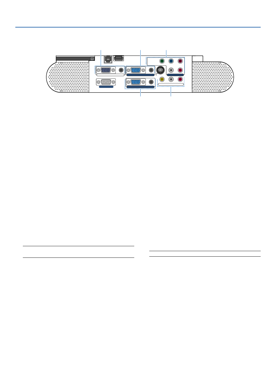
Terminal Panel Features
1. COMPUTER 1 Input Connector (Mini D-Sub 15 Pin)
Connect your computer or other analog RGB equip-
ment such as IBM compatible or Macintosh comput-
ers. Use the supplied RGB cable to connect to your
computer.
COMPUTER 1 AUDIO Input Mini Jack (Stereo Mini)
This is where you connect the audio output from your
computer when connected to the COMPUTER 1 in-
put. A commercially available audio cable is required.
2. COMPUTER 2 Input Connector (Mini D-Sub 15 Pin)
Connect your computer or other analog RGB equip-
ment such as IBM compatible or Macintosh comput-
ers. Use the supplied RGB cable to connect to your
computer.
This connector also supports SCART output signal.
The SCART cable is sold separately.
See page 24 for more details.
NOTE: The COMPUTER 2 Input does not support Plug &
Play.
COMPUTER 2 AUDIO Input Mini Jack (Stereo Mini)
This is where you connect the audio output from your
computer when connected to the COMPUTER 2 in-
put. A commercially available audio cable is required.
3. MONITOR OUT Connector (Mini D-Sub 15 Pin)
You can use this connector to loop your computer
image to an external monitor from the COMPUTER
1/2 or component video input source.
This connector also outputs a COMPUTER signal
or component signal in Idle mode.
AUDIO OUT Mini Jack (Stereo Mini)
You can use this jack to output sound from the cur-
rently selected source (COMPUTER 1/2, COMPO-
NENT, VIDEO or S-VIDEO). The current or last dis-
played source's audio will be sent to the audio output
even in Idle mode.
Output sound level (volume, bass/treble and mute)
can be adjusted in accordance with the sound level
of the internal speaker.
Output sound level (volume, bass/treble and mute)
cannot be adjusted in Idle mode.
Note that this cannot be used as a headphone jack.
(When audio equipment is connected, the projector
speaker is disabled.)
4. COMPONENT (Y, Cb/Pb, Cr/Pr) Input Connectors
(RCA)
Connect component video outputs (Y/Cb/Cr, Y/Pb/Pr)
of the external equipment such as DVD player.
NOTE: The “Y” connector accepts Video signal.
COMPONENT AUDIO Input Jacks R/L (RCA)
These are your left and right channel audio inputs for
stereo sound from your DVD player or component
equipment connected to COMPONENT Input Connec-
tors.
5. VIDEO Input Connector (RCA)
Connect a VCR, DVD player, laser disc player, or docu-
ment camera here to project video.
VIDEO/S-VIDEO AUDIO Input Jacks R/L (RCA)
These are your left and right channel audio inputs for
stereo sound from a Video or S-Video source.