7sv7 hardware manual, Screw terminal connector, Motor – Applied Motion SV7-C-CE User Manual
Page 7: Power supply db-25 connector, Digital inputs, Digital outputs, Analog input communication option, Rs-485, Ethernet, Canopen
7
SV7 Hardware Manual
920-0012F
12/18/2014
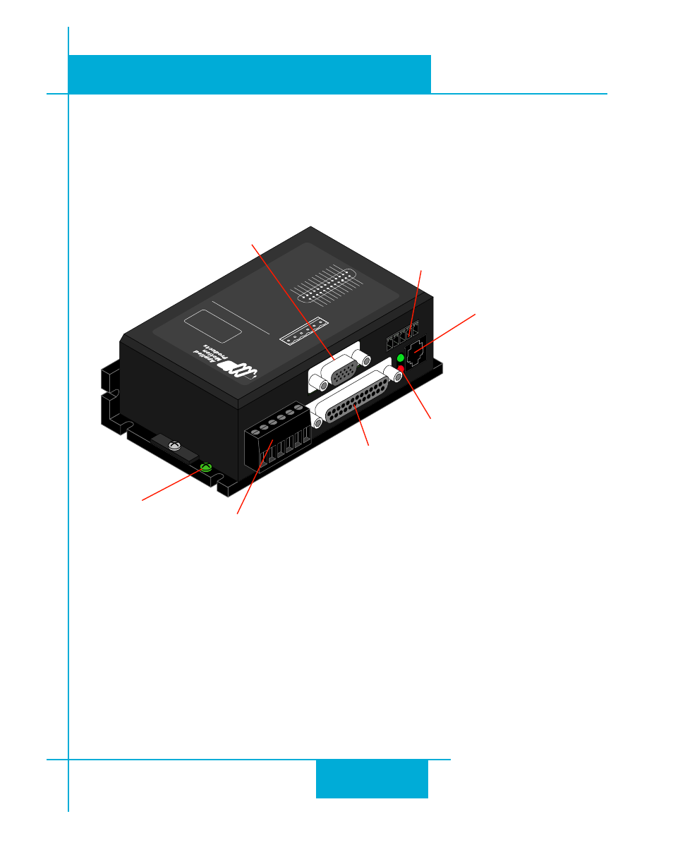
The connectors and other points of interest are illustrated below. Depending on your drive model
and application, you’ll need to make connections to various parts of the drive. These are detailed
later in the manual.
C
B
A
V-
V+
V-
V+
LED Codes
GR=Green
RD=Red
MOTOR DISABLED
SOLID GREEN
MOTOR ENABLED
GR-GR-GR
MOTOR STALL
1 GR + 1 RD
CCW LIMIT
1 GR + 2 RD
CW LIMIT
2 GR + 2 RD
CAN’T MOVE (DISABLED)
2 GR + 1 RD
DRIVE OVER TEMP
1 GR + 3 RD
VO
LTAGE HIGH
1 GR + 4 RD
VO
LTAGE LOW
2 GR + 4 RD
OVER CURRENT
1 GR + 5 RD
MOTOR OHMS
2 GR + 5 RD
OPEN MOTOR PHASE
1 GR + 6 RD
BAD ENCODER SIGNAL
2 GR + 6 RD
COMM ERROR
1 GR + 7 RD
GN
D
+5V
O
UT
Y C
OM
MO
N
Y3
/ F
AU
LT
Y2
/ M
OT
IO
N
Y1
/ B
RA
KE
X8
/ C
CW
LIM
IT+
X8
/ C
CW
LIM
IT
-
X7
/ C
WL
IM
IT
-
X7
/ C
WL
IM
IT+
Y4
-
Y4+
25
24
23
22
21
20
19
18
17
16
15
14
13
12
11
10
9
8
7
6
5
4
3
2
1
X C
OM
MO
N
X3
/ E
NA
BLE
X5
/ C
WJ
OG
X4
/ A
LAR
M R
ESE
T
AN
ALO
G I
N2
AN
ALO
G I
N1
X2
/ D
IR
-
X2
/ D
IR+
X1
/ S
TEP
+
X1
/ S
TEP
-
GN
D
X6
/ C
CW
JOG
Serial No
SV
7-Q
SERVO MOTOR
DRIVER
screw terminal
connector
•
motor
•
power supply
DB-25 connector
•
digital inputs
•
digital outputs
•
analog input
communication option
•
RS-485
•
Ethernet
•
CANopen
•
Motion Controller Feedback (MCF)
HD-15 connector
•
encoder feedback
RJ11 connector
•
RS-232 port
(not used on Ethernet model)
LEDs
•
status & error codes
grounding
screw
For applications requiring encoder outputs to a motion controller, please request the
Motion Controller Feedback (MCF) option.