Using high speed inputs with 12-24 volt signals, 28 sv7 hardware manual – Applied Motion SV7-C-CE User Manual
Page 28
28
SV7 Hardware Manual
920-0012F
12/18/2014
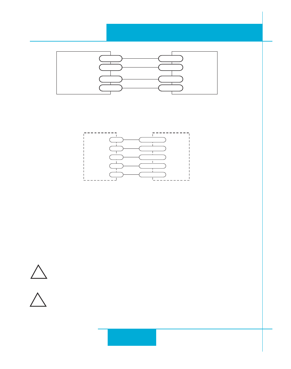
Wiring for Encoder Following
Using High Speed Inputs with 12-24 Volt Signals
Most PLCs don’t use 5 volt logic. You can connect signal levels as high as 24 volts to the STEP and
DIR inputs if you add external dropping resistors, as shown below.
• For 12 volt logic, add 820 ohm, 1/4 watt resistors
• For 24 volt logic, use 2200 ohm, 1/4 watt resistors
The maximum voltage that can be applied to an input terminal is 24 volts
DC. Never apply AC voltage to an input terminal.
The pulse and direction wiring can pick up noise especially if resistors are
placed on terminal strips next to “noisy” wiring, resulting in stray step
pulses and a loss of position accuracy.
IN/OUT1
Master
Encoder
GND
X2/DIR-
X2/DIR+
X1/STEP-
X1/STEP+
GND
B-
B+
A-
A+
Connecting to Indexer with Differential Outputs
(Many High Speed Indexers have Differential Outputs)
IN/OUT 1
DIR+
X2/DIR+
DIR-
X2/DIR-
X1/STEP+
STEP-
STEP+
X1/STEP-
Indexer
with
Differential
Outputs
!
!