Connecting limit switches, 32 sv7 hardware manual – Applied Motion SV7-C-CE User Manual
Page 32
32
SV7 Hardware Manual
920-0012F
12/18/2014
Connecting a PNP Type Proximity Sensor to a an input
(When prox sensor activates, input goes low).
IN/OUT1
PNP
Proximity
Sensor
X3..X6
output
+
–
XCOM
12-24
VDC
Power
Supply
-
+
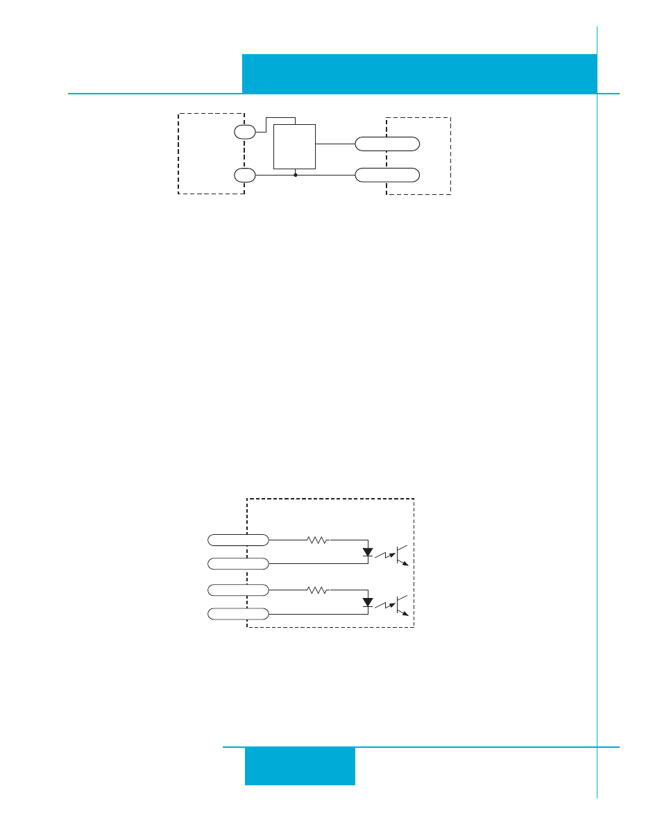
Connecting Limit Switches
The CWLIMIT and CCWLIMIT inputs are used for connecting end of travel sensors. These inputs
can be driven by signals that are sinking (NPN), sourcing (PNP) or differential (line driver). By con-
necting switches or sensors that are triggered by the motion of the motor or load, you can force
the motor to operate within certain limits. This is useful if a program or operator error could cause
damage to your system by traveling too far.
The limit inputs are optically isolated. This allows you to choose a voltage for your limit circuits of
12 to 24 volts DC. This also allows you to have long wires on limit sensors that may be far from the
drive with less risk of introducing noise to the drive electronics. The schematic diagram of the limit
switch input circuit is shown below.
inside drive
IN/OUT 1 Connector
2200
X8/CCWLIM-
25
X8/CCWLIM+
24
2200
X7/CWLIM-
23
X7/CWLIM+
22