Wiring integral holding brakes, 36 sv7 hardware manual – Applied Motion SV7-C-CE User Manual
Page 36
36
SV7 Hardware Manual
920-0012F
12/18/2014
Wiring Integral Holding Brakes
The integral holding brakes of AMP servo motors require between 200 and 400 mA at 24 VDC to
operate properly. To wire and operate a holding brake from the Y1/Brake output of an Applied
Motion servo drive requires the following items:
• A 24 VDC power supply with minimum output of 450 mA
• A 24 VDC relay*
• A clamp diode such as 1N4935*
• An AMP servo motor with integral holding brake, designated by a “5” in the 7th position of the
motor part number. Example: M0400-151-4-000
• A “BK” type motor power cable or separate brake cable. Example: BLUMTR-BK-FA-10
* Relays with an integral clamp diode, like IDEC part number RU2S-D-D24, greatly simplify the wir-
ing effort by including the relay and a clamp diode in one unit.
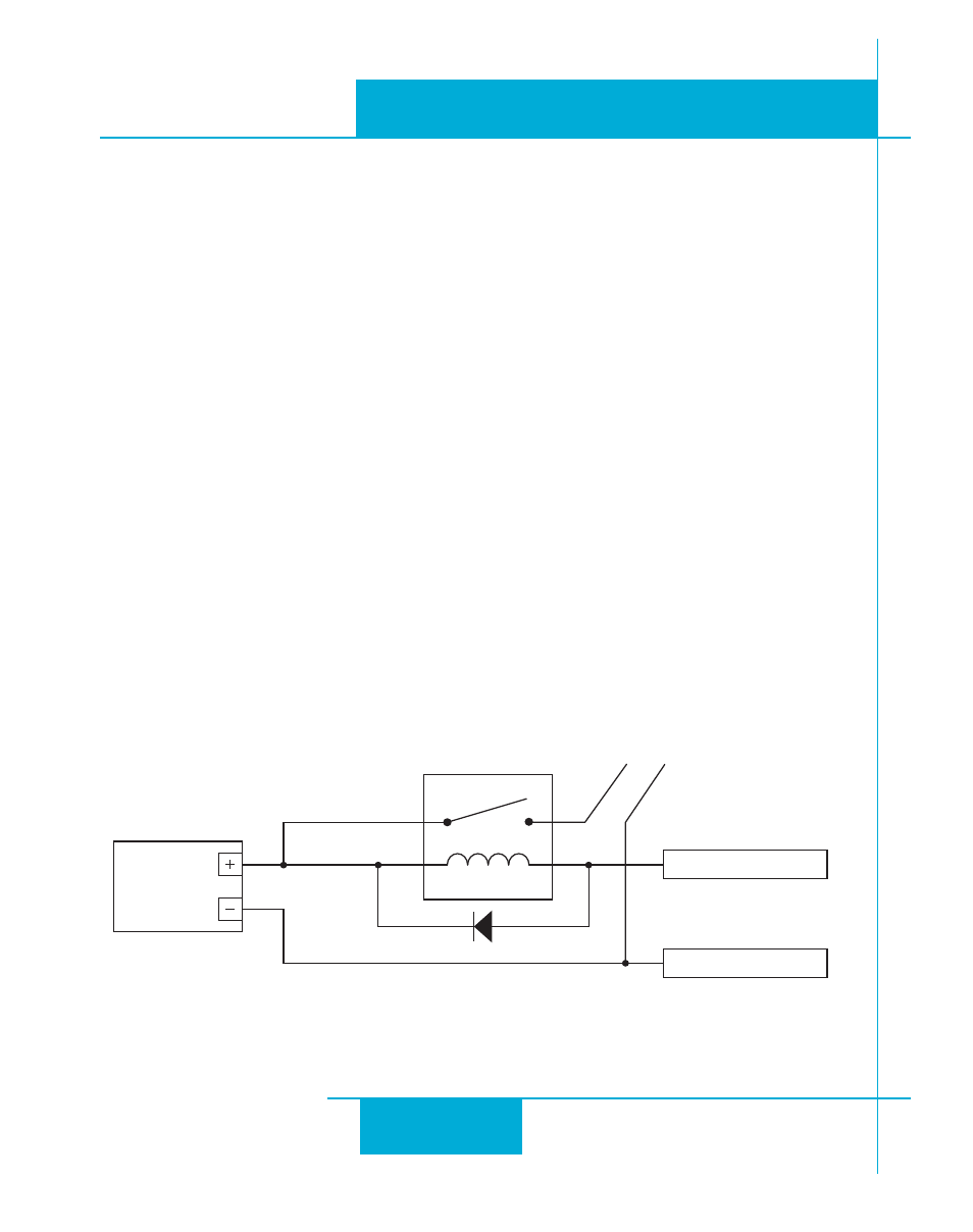
Following the diagram below, connect the power supply, relay, and diode to the brake leads of the
servo motor, as well as the Y1/Brake output connections of the servo drive.
Y COMMON (pin 17)
Y1 / Brake (pin 14)
24 VDC
power
supply
BLUE br
ak
e lead
YELLO
W br
ak
e lead
24 VDC relay
clamp diode