24 sv7 hardware manual, Front view, Internal encoder circuits – Applied Motion SV7-C-CE User Manual
Page 24: Pin assignments (facing drive)
24
SV7 Hardware Manual
920-0012F
12/18/2014
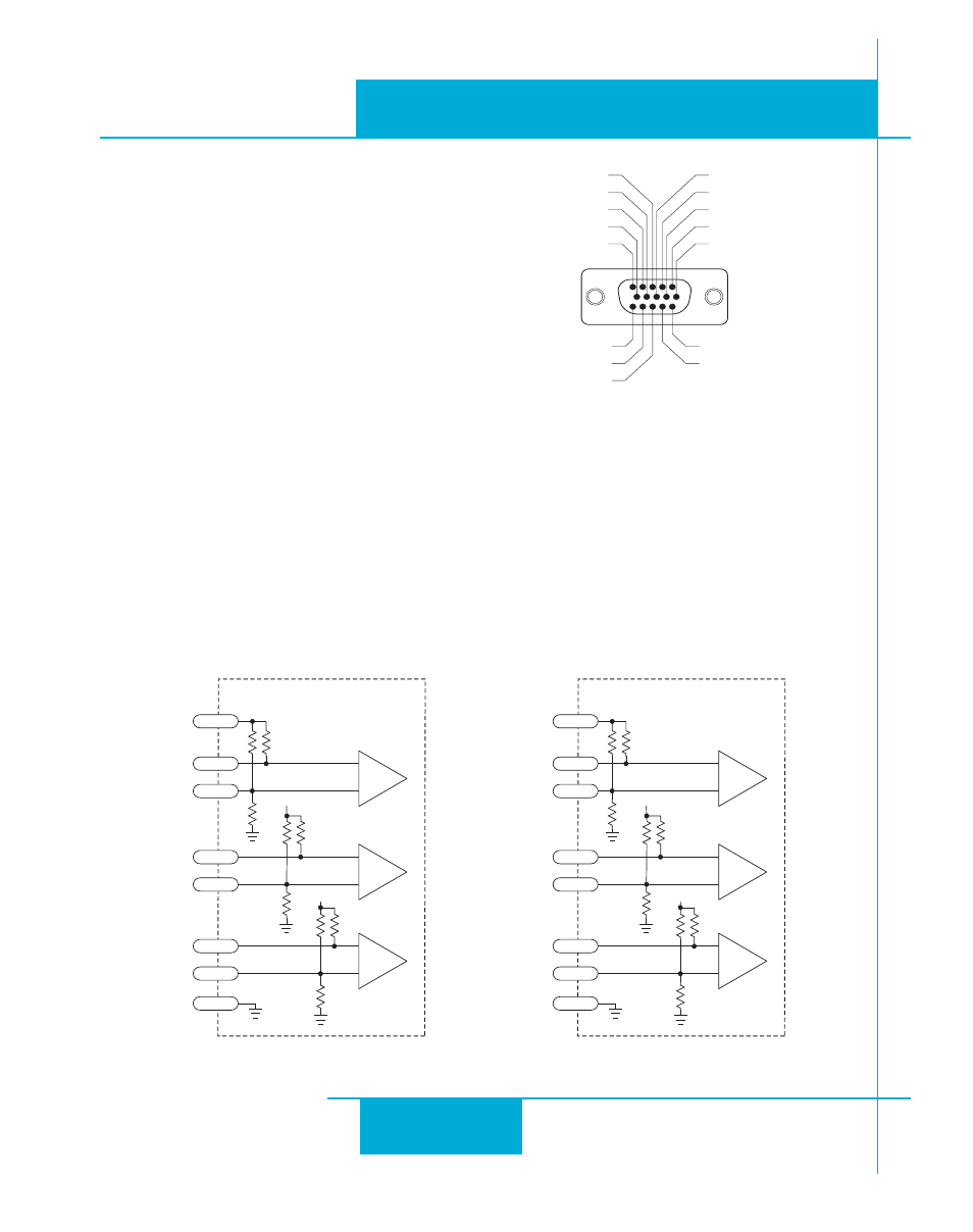
Internal Encoder Circuits
inside drive
A-
A+
2
GND
8
1
+5V
7
HD-15 Connector
B-
B+
4
3
Z-
Z+
6
5
5K
12.5K
8.3K
5K
12.5K
8.3K
5K
+5V
+5V
12.5K
8.3K
inside drive
H1-
H1+
10
GND
15
9
+5V
7
HD-15 Connector
H2-
H2+
12
11
H3-
H3+
14
13
499
830
1.25K
499
830
1.25K
499
+5V
+5V
830
1.25K
Non-Applied Motion motor:
Connect the motor leads to the screw terminal con-
nector as follows:
A = motor phase A, R or U
B = motor phase B, S or V
C = motor phase C, T or W
chassis ground screw = green wire
The encoder connections use a HD-15 connector,
which you must connect to your encoder as shown
on the right. See
Accessories for mating connector
information.
If your encoder is single ended, connect the encoder outputs to the A+, B+ and Z+ inputs. Leave
A-, B- and Z- unconnected. (Z is the encoder index signal and is optional.)
Single-end halls should also be connected to the “+” inputs with the “-” inputs left unconnected.
Pin Assignments (facing drive)
encoder Z+ (5)
Hall 1-(10)
encoder B- (4)
Hall 1+ (9)
encoder B+ (3)
Hall 3+ (13)
Hall 3- (14)
GND (15)
(12) Hall 2-
(11) Hall 2+
(6) encoder Z-
(1) encoder A+
(7) +5VDC 200mA
(2) encoder A-
(8) GND
Front View