Connecting input signals, Connector pin diagram, 26 sv7 hardware manual – Applied Motion SV7-C-CE User Manual
Page 26
26
SV7 Hardware Manual
920-0012F
12/18/2014
Connecting Input Signals
The SV drives have 8 digital inputs and 2 analog inputs categorized as follows:
· Two high speed digital inputs, 5 volt logic: X1/STEP and X2/DIR.
Digital signals for commanding position. Quadrature signals from encoders can also be used. These
inputs can also be connected to sensors, switches and other devices for use with Q and Si™ com-
mands such as Wait input, Seek Home, Feed to Sensor, If Input and others.
· Four single-ended digital inputs, 12-24 volt logic: X3, X4, X5, and X6.
Software programmable inputs can be used for motor enable, alarm reset or jogging. These inputs
can also be connected to sensors, switches and other devices for use with Q and Si™ Wait Input,
Seek Home, Feed to Sensor, If Input and other commands.
· Two differential digital inputs, 12-24 volt logic: X7/CWLIMIT and X8/CCWLIMIT.
Can be used to inhibit motion in a given direction, forcing the motor and load to travel within
mechanical limits. Can be configured for active closed, active open, or not used which makes the
inputs act as general purpose inputs.
· Two single-ended analog inputs, +/-10 volt logic: Analog IN1 and Analog IN2.
Support 0-10, +/-5, or 0-5 volt logic as well. Can be wired together to create one differential ana-
log input. Analog velocity or position command signal. Note: the analog inputs are currently not
supported by the
Si Programmer™ software.
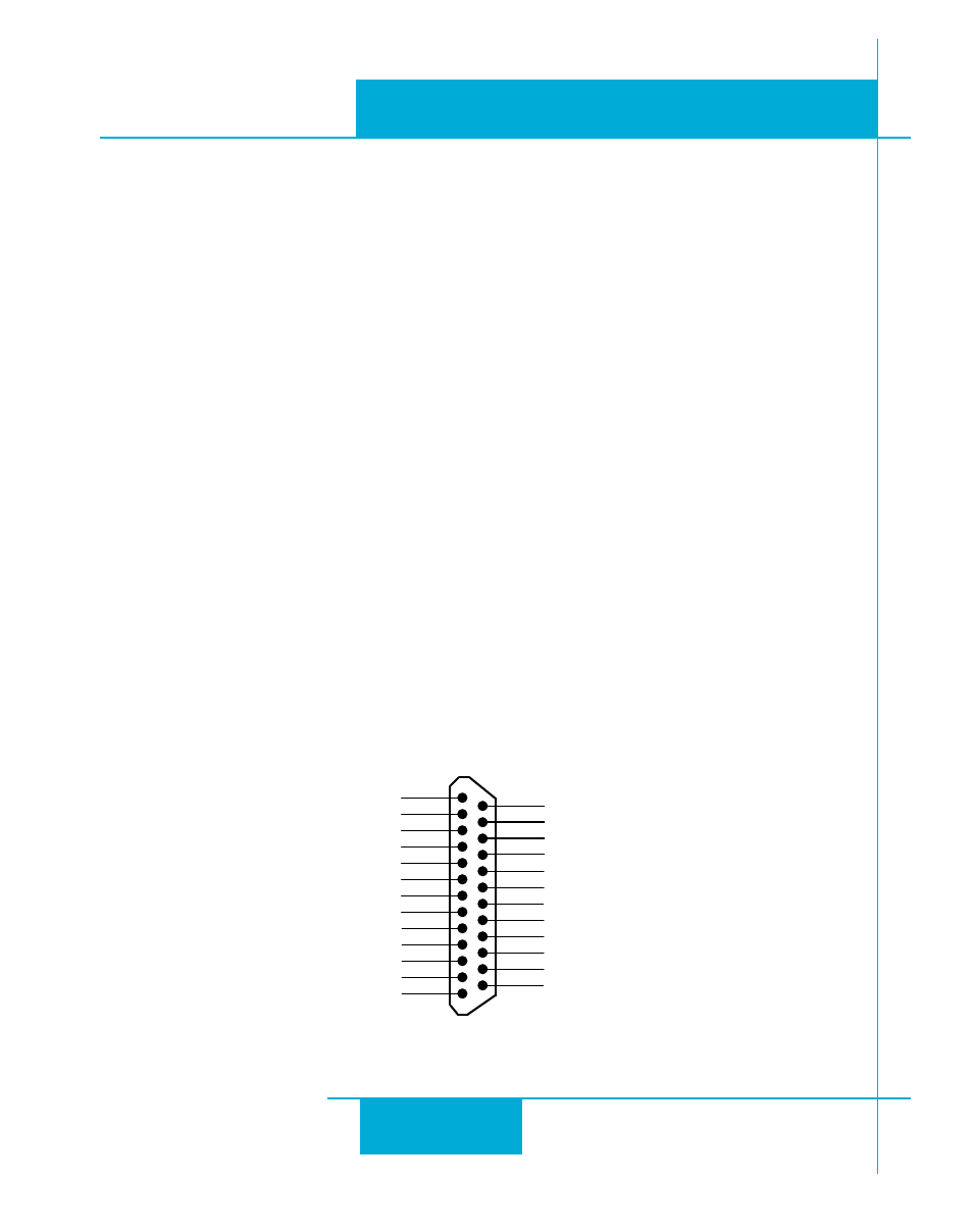
Connector Pin Diagram
IN/OUT1 (DB-25) Connector
Front View
X COMMON
not used
X3 / Enable
X5 / CWJOG
X4 / Alarm Reset
Analog IN2
Analog IN1
X2 / DIR-
X2 / DIR+
X1 / STEP +
X1 / STEP -
GND
GND
+5V OUT
Y COMMON
Y3 / FAULT
Y2 / MOTION
Y1 / BRAKE
1 8
1 7
1 6
1 5
1 4
1 3
1 2
1 1
1 0
9
8
7
6
5
4
2
3
1
1 9
2 0
2 1
2 2
2 3
2 4
2 5
X6 / CCWJOG
IN/OUT
X8/CCWLIMIT+
X8/CCWLIMIT-
X7/CWLIMIT-
X7/CWLIMIT+
Y4-
Y4+