Power supply, Power supply –39 – Altera Transceiver Signal Integrity Development Kit, Stratix V GX Edition User Manual
Page 47
Chapter 2: Board Components
2–39
Power Supply
July 2012
Altera Corporation
Transceiver Signal Integrity Development Kit
Stratix V GX Edition Reference Manual
Power Supply
A laptop style DC power input provides power to the development board. The input
voltage must be in the range of 14 V to 20 V. The DC voltage is then stepped down to
the various power rails used by the components on the board.
An on-board multi-channel power monitor device (LTC2978) measures both the
voltage and current for several specific board rails. This device has the capability to
trim voltage outputs ±10%.
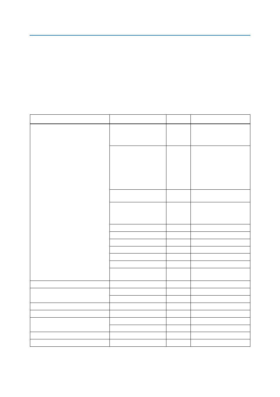
lists the power requirements for each major component on the board.
Table 2–40. Power Requirements
Device
Voltage Name
Voltage (V)
Note
FPGA
S5GX_VCC
0.9
VCC
VCCHIP
VCCHSSI
2p5V
2.5
VCCIO
VCCPD
VCCREF
VCCPGM
VCCBAT
VCC_CLKIN
2p5V_FLTR
2.5
Ferrite fitered from 2p5V,
VCCA_PLL, and VCCAUX
1p5V
1.5
VCCPT
VCCH_GXB
VCCD_FPLL
VCCBAT
1.5
BT1 socket
VCCR_GTB (28G channels)
1.0
LDO
VCCT_GTB (28G channels)
1.0
LDO
VCCL_GTB (28G channels)
1.0
LDO
VCCRT_GXB
0.9 or 1.0
Low noise switcher
VCCA_GXB
2.5 or 3.0
Low noise switcher
VCCH_GXB
1.5
Tied to 1p5V (low noise
switcher)
MAX II (for FPP configuration)
2p5V
2.5
—
Flash
2p5V
2.5
Core
XFP_1p8V
1.8
I/O
MAX II (for USB-Blaster)
2p5V
2.5
Core or I/O
EEPROM
USBVCC
5.0
—
USB PHY
USBVCC
5.0
Core
2p5V_USB
2.5
I/O
Power monitor
5V
5.0
—
Temperature sense ADC
3p3V
3.3
—