Fpga programming over external usb-blaster, Status elements, Fpga programming over external usb-blaster –16 – Altera Stratix IV GX FPGA Development Board User Manual
Page 24: Status elements –16
2–16
Chapter 2: Board Components
Configuration, Status, and Setup Elements
Stratix IV GX FPGA Development Board, 530 Edition Reference Manual
November 2010
Altera Corporation
There are two pages reserved for the FPGA configuration data. The factory hardware
page is considered page 0 and is loaded if the rotary switch is in position 0 and when
either power is cycled or the reset configuration push-button switch (S1) is pressed.
The user hardware page is considered page 1 and is loaded if the rotary switch is in
position 1 and when either power is cycled or the reset configuration push-button
switch (S1) is pressed.
FPGA Programming over External USB-Blaster
The JTAG programming header provides another method for configuring the FPGA
(U13) using an external USB-Blaster device with the Quartus II Programmer running
on a PC. The external USB-Blaster is connected to the board through the JTAG
connector (J8). The JTAG DIP switch (SW6) allows the MAX II CPLD device to be
removed from the JTAG chain so that the FPGA is the only device on the JTAG chain.
f
For more information on the following topics, refer to the respective documents:
■
Board Update Portal, re
.
■
PFL design, refer to the
■
PFL megafunction, refer to
Status Elements
The development board includes status LEDs. This section describes the status
elements.
lists the LED board references, names, and functional descriptions.
Board Information
32
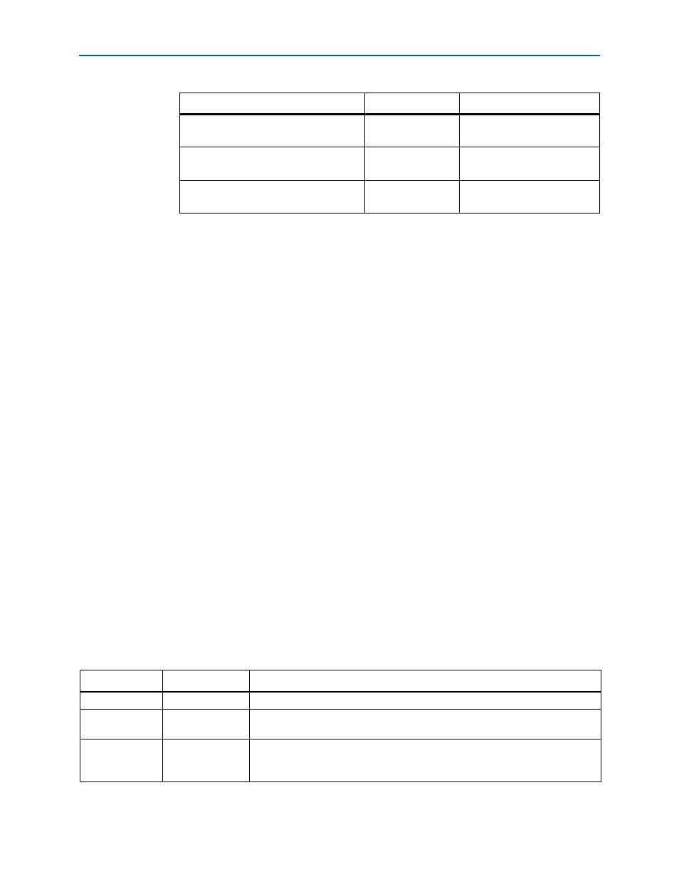
0x00010000 – 0x00017FFF
Ethernet Option Bits
32
0x00008000 – 0x0000FFFF
User Design Reset Vector
32
0x00000000 – 0x00007FFF
Table 2–8. Flash Memory Map (Part 2 of 2)
Name
Size (Kbyte)
Address
Table 2–9. Board-Specific LEDs (Part 1 of 2)
Board Reference
LED Name
Description
D24
POWER
Blue LED. Illuminates when 3.3-V power is active.
D5
CONF DONE
Green LED. Illuminates when the FPGA is successfully configured. Driven by the
MAX II CPLD EPM2210 System Controller.
D26
Loading
Green LED. Illuminates when the MAX II CPLD EPM2210 System Controller is
actively configuring the FPGA. Driven by the MAX II CPLD EPM2210 System
Controller wire-OR'd with the Embedded Blaster CPLD.