Sdi tx channels, Sdi tx channels –15 – Altera SDI HSMC User Manual
Page 23
Chapter 2: Board Components
2–15
Audio/Video Input and Output
© July 2009 Altera Corporation
SDI TX Channels
The SDI TX channel consists of a SDI cable tri-speed driver (LMH0302) with slew rate
control, an output impedance matching network, an output vertical mount with a
4-GHz BNC connector, an SDI rate select control signal, DC blocking caps on the input
and output, and a red/green LED.
f
For the TX channel circuit diagram, refer to the schematic page entitled SDI Cable
Driver on page 5 of Altera schematic 150-0320610-B1. In Altera development kits that
contain the SDI HSMC, this schematic resides in the <install dir>\board_design_files
directory.
The SDI_RATE_SEL signal is driven from the host device through the HSMC
connector pins 71 and 73. These pins should not be allowed to float. A logic 1 reduces
the slew rate to match the SD-SDI signaling requirements while a logic 0 increases the
output slew rate of the SDI cable driver and is used when transmitting 1.485 Gbps rate
(HD) and 2.970 Gbps rate (3G).
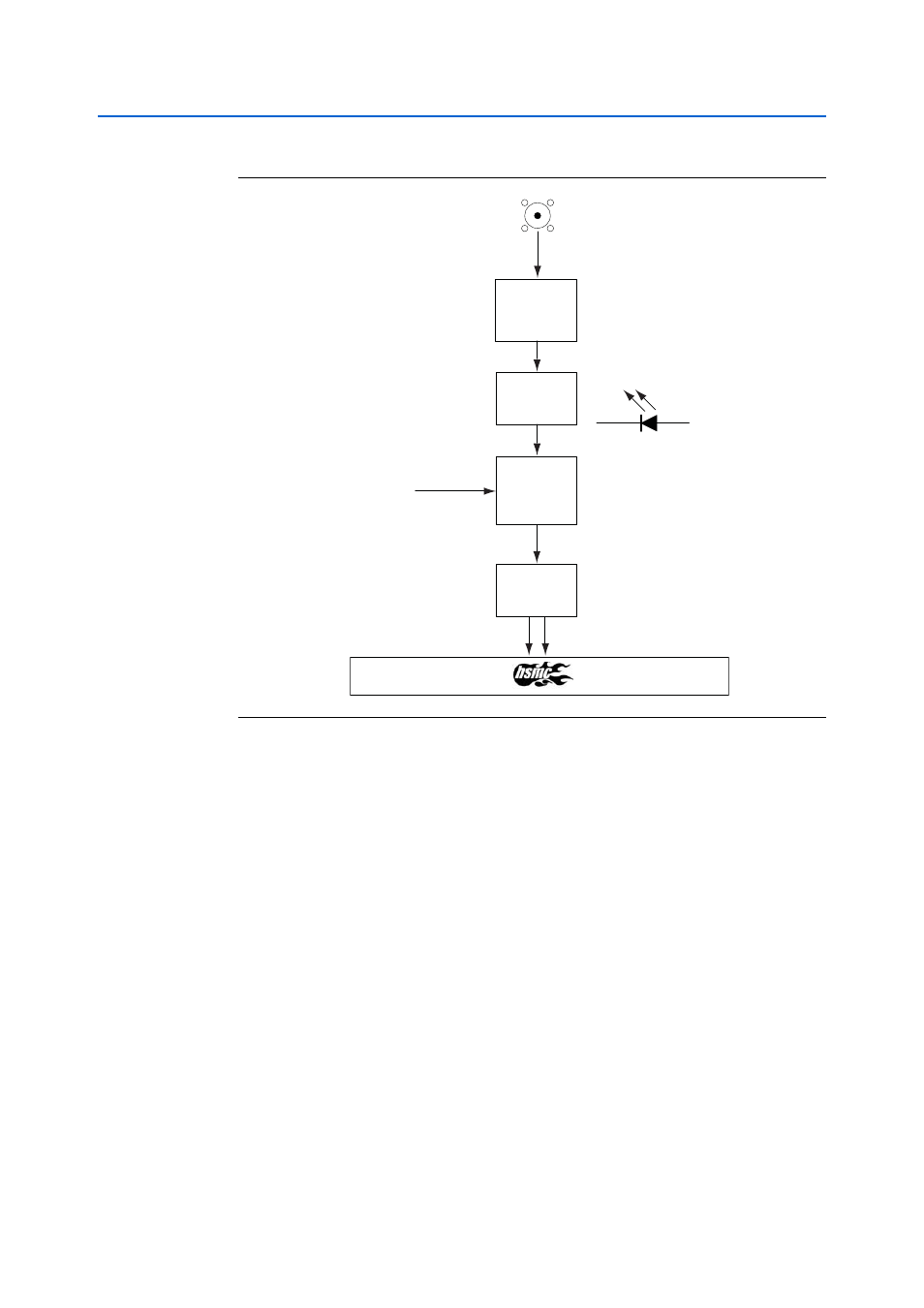
Figure 2–7. SDI RX Channel Block Diagram
bypass
SDI Cable
Equalizer
LR
Network + Term
SDI RX
Carrier Detect
DC Block
DC Block